AT91SAM9G45-EKES Atmel, AT91SAM9G45-EKES Datasheet - Page 35
AT91SAM9G45-EKES
Manufacturer Part Number
AT91SAM9G45-EKES
Description
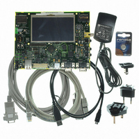
KIT EVAL FOR AT91SAM9G45
Manufacturer
Atmel
Series
AT91SAM Smart ARMr
Type
MCUr
Datasheets
1.AT91SAM9G45-EKES.pdf
(56 pages)
2.AT91SAM9G45-EKES.pdf
(1218 pages)
3.AT91SAM9G45-EKES.pdf
(66 pages)
Specifications of AT91SAM9G45-EKES
Contents
Board
Processor To Be Evaluated
SAM9G45
Data Bus Width
32 bit
Interface Type
I2C, SPI, UART
Maximum Operating Temperature
+ 50 C
Minimum Operating Temperature
- 10 C
Operating Supply Voltage
1.8 V to 3.3 V
For Use With/related Products
AT91SAM9G45
Lead Free Status / RoHS Status
Lead free / RoHS Compliant
Other names
Q4626953


5.4
5.5
5.5.1
AT91SAM9G45-EKES User Guide
Miscellaneous Configuration Items
PIO Configuration
Peripheral Signals Multiplexing on I/O Lines
N.P = not populated
P = populated
Table 5-3. Miscellaneous Configuration
The AT91SAMG45 product features 5 PIO controllers, PIOA, PIOB, PIOC, PIOD and PIOE, which multi-
plex the I/O lines of the peripheral set. Each PIO Controller controls up to 32 lines. Each line can be
assigned to one of two peripheral functions, A or B. The multiplexing tables in the following paragraphs
define how the I/O lines of peripherals A and B are multiplexed on the PIO Controllers.
Designation
R100, R101
R102,R103
R104,R107
R92, R93,
R94, R95,
Y6, R122,
R58, R59
R75, R77
R69, R70
R98, R99
R84,R85
R86,R87
R112
R124
R20
R21
R22
R24
R47
R55
R60
TP1
TP2
TP3
TP4
Default
Setting
N.P
N.P
N.P
N.P
N.P
N.P
N.P
P
P
P
JTAGSEL
Connect TSADVREF to VDDANA (may be used for specific filtering)
Connect GNDANA to GND (may be used for specific filtering)
Force TST pin to GND (chip is set in non-test mode = normal operation mode)
Write protect NAND Flash (mount a 0-ohm resistor to write-protect the NAND
Flash device)
Write protect serial Data Flash (mount a 0-ohm resistor to write-protect the serial
Flash device)
Clock selection Audio AC97 (see mapping table in
External clock Audio AC97 (mount a 0-ohm resistor to connect it)
Change bias from VREFOUT (see
Voice filter components
ICE interface reset and clocking schemes (see
Configuration”
Ethernet interface, MII mode (see
External 13 MHz oscillator (option) for the on-board video composite encoder
GND Test point
GND Test point
GND Test point
GND Test point
)
Section 5.2 ”ETHERNET Configuration”
Section 7.1 ”Schematics”
Feature
Section 5.1 ”JTAG/ICE
Section 7.1 ”Schematics”
6481B–ATARM–27-Nov-09
)
Configuration
)
5-3
)
Related parts for AT91SAM9G45-EKES
Image
Part Number
Description
Manufacturer
Datasheet
Request
R

Part Number:
Description:
MCU ARM9 64K SRAM 144-LFBGA
Manufacturer:
Atmel
Datasheet:

Part Number:
Description:
IC ARM7 MCU FLASH 256K 100LQFP
Manufacturer:
Atmel
Datasheet:

Part Number:
Description:
IC ARM9 MPU 217-LFBGA
Manufacturer:
Atmel
Datasheet:
Part Number:
Description:
MCU ARM9 ULTRA LOW PWR 217-LFBGA
Manufacturer:
Atmel
Datasheet:

Part Number:
Description:
MCU ARM9 324-TFBGA
Manufacturer:
Atmel
Datasheet:
Part Number:
Description:
IC MCU ARM9 SAMPLING 217CBGA
Manufacturer:
Atmel
Datasheet:
Part Number:
Description:
IC ARM9 MCU 217-LFBGA
Manufacturer:
Atmel
Datasheet:

Part Number:
Description:
IC ARM9 MCU 208-PQFP
Manufacturer:
Atmel
Datasheet:
Part Number:
Description:
MCU ARM 512K HS FLASH 100-LQFP
Manufacturer:
Atmel
Datasheet:

Part Number:
Description:
MCU ARM 512K HS FLASH 100-TFBGA
Manufacturer:
Atmel
Datasheet:
Part Number:
Description:
IC ARM9 MCU 200 MHZ 324-TFBGA
Manufacturer:
Atmel
Datasheet:

Part Number:
Description:
IC ARM MCU 16BIT 128K 256BGA
Manufacturer:
Atmel
Datasheet:

Part Number:
Description:
IC ARM7 MCU 32BIT 128K 64LQFP
Manufacturer:
Atmel
Datasheet:

Part Number:
Description:
IC ARM7 MCU FLASH 256K 128-LQFP
Manufacturer:
Atmel
Datasheet:
Part Number:
Description:
IC ARM7 MCU FLASH 512K 128-LQFP
Manufacturer:
Atmel
Datasheet: