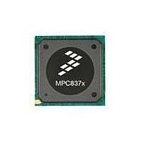
MPC8377E-RDBA Freescale Semiconductor, MPC8377E-RDBA Datasheet - Page 109

MPC8377E-RDBA
Manufacturer Part Number
MPC8377E-RDBA
Description
BOARD REF DES MPC8377 REV 2.1
Manufacturer
Freescale Semiconductor
Series
PowerQUICC II™ PROr
Type
MPUr
Datasheets
1.MPC8377EVRAGD.pdf
(126 pages)
2.MPC8377EVRAGD.pdf
(2 pages)
3.MPC8377E-RDBA.pdf
(2 pages)
Specifications of MPC8377E-RDBA
Design Resources
MPC8379E-RDB Ref Design Guide
Contents
Board, CD
Frequency
667 MHz
For Use With/related Products
MPC8377E
Lead Free Status / RoHS Status
Lead free / RoHS Compliant
- Current page: 109 of 126
- Download datasheet (3Mb)
23.1
The system PLL is controlled by the RCWLR[SPMF] parameter. The system PLL VCO frequency
depends on RCWLR[DDRCM] and RCWLR[LBCM].
for the system PLL.
As described in
configuration word low and the CFG_CLKIN_DIV configuration input signal select the ratio between the
primary clock input (CLKIN or PCI_CLK) and the internal coherent system bus clock (csb_clk).
and
CLKIN/PCI_SYNC_IN ratios.
The RCWLR[SVCOD] denotes the system PLL VCO internal frequency as shown in
Freescale Semiconductor
Table 78
System PLL Configuration
show the expected frequency values for the CSB frequency for select csb_clk to
If RCWLR[DDRCM] and RCWLR[LBCM] are both cleared, the system
PLL VCO frequency = (CSB frequency) × (System PLL VCO Divider).
If either RCWLR[DDRCM] or RCWLR[LBCM] are set, the system PLL
VCO frequency = 2 × (CSB frequency) × (System PLL VCO Divider).
The VCO divider needs to be set properly so that the System PLL VCO
frequency is in the range of 400–800 MHz.
Section 23, “Clocking,”
RCWLR[SVCOD]
RCWLR[SPMF]
MPC8377E PowerQUICC II Pro Processor Hardware Specifications, Rev. 4
0111–1111
0000
0001
0010
0011
0100
0101
0110
00
01
10
11
Table 75. System PLL Multiplication Factors
Table 76. System PLL VCO Divider
The LBIUCM, DDRCM, and SPMF parameters in the reset
NOTE
Table 75
shows the multiplication factor encodings
System PLL Multiplication Factor
VCO Division Factor
× 7 to × 15
Reserved
Reserved
× 2
× 3
× 4
× 5
× 6
4
8
2
1
Table
76.
Table 77
Clocking
109
Related parts for MPC8377E-RDBA
Image
Part Number
Description
Manufacturer
Datasheet
Request
R
Part Number:
Description:
BOARD MODULAR DEV SYSTEM
Manufacturer:
Freescale Semiconductor
Datasheet:
Part Number:
Description:
PowerQUICC II Pro Processor
Manufacturer:
Freescale Semiconductor
Part Number:
Description:
Manufacturer:
Freescale Semiconductor, Inc
Datasheet:
Part Number:
Description:
Manufacturer:
Freescale Semiconductor, Inc
Datasheet:
Part Number:
Description:
Manufacturer:
Freescale Semiconductor, Inc
Datasheet:
Part Number:
Description:
Manufacturer:
Freescale Semiconductor, Inc
Datasheet:
Part Number:
Description:
Manufacturer:
Freescale Semiconductor, Inc
Datasheet:
Part Number:
Description:
Manufacturer:
Freescale Semiconductor, Inc
Datasheet:
Part Number:
Description:
Manufacturer:
Freescale Semiconductor, Inc
Datasheet:
Part Number:
Description:
Manufacturer:
Freescale Semiconductor, Inc
Datasheet:
Part Number:
Description:
Manufacturer:
Freescale Semiconductor, Inc
Datasheet:
Part Number:
Description:
Manufacturer:
Freescale Semiconductor, Inc
Datasheet:
Part Number:
Description:
Manufacturer:
Freescale Semiconductor, Inc
Datasheet:
Part Number:
Description:
Manufacturer:
Freescale Semiconductor, Inc
Datasheet:
Part Number:
Description:
Manufacturer:
Freescale Semiconductor, Inc
Datasheet:


