EDK7145 Renesas Electronics America, EDK7145 Datasheet - Page 10
EDK7145
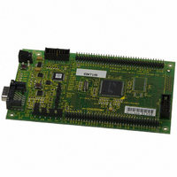
Manufacturer Part Number
EDK7145
Description
DEV EVALUATION KIT SH7145
Manufacturer
Renesas Electronics America
Type
MCUr
Datasheets
1.EDK7145.pdf
(19 pages)
2.EDK7145.pdf
(4 pages)
3.EDK7145.pdf
(5 pages)
4.EDK7145.pdf
(22 pages)
Specifications of EDK7145
Contents
2G (Second-generation) Evaluation Board, HEW debugger support, Cable and CD-ROM
Lead Free Status / RoHS Status
Contains lead / RoHS non-compliant
For Use With/related Products
SH7145
Lead Free Status / RoHS Status
Not Compliant, Contains lead / RoHS non-compliant


The default settings indicated in bold text place the microcontroller into operating Mode 3, i.e. on-chip ROM enabled, single
chip mode and clock mode 3: System clock = x4, Peripheral clock = x2.
5.3. EDK O
The EDK options provide access to commonly used features of the EDK range.
These jumpers must be fitted at all times to ensure correct operation of the EDK.
*
The following table lists the connections to each jumper pin.
5.4. S
The programming serial port is connected to the RS232 connector by default. This allows direct programming of the EDK
using the supplied software tools. A secondary serial port is available on the microcontroller and can be connected to the
RS232 connector by changing some board option links. The additional port option allows the user to write messages or
connect to other devices via the serial port while programming support is provided by the Flash programming header.
The following surface mount, zero-ohm link settings are fitted by default and connect the RS232 header to the programming
serial port of the microcontroller.
1
See section 5.5
ERIAL
CJ 4-A
Default 2-3
CJ 4-B
Default 2-3
CJ 4-C
Default 2-3
CJ 4-D
Default 1-2
1
2
3
4
5
6
7
8
9
10
11
12
Pin
Jumper
PTIONS
P
CR20
CR23
CR19
CR22
ORT
Zero-ohm
Link ID
UVCC
RXDISn
No Connection
UVCC
UPM
No Connection
No Connection
DBGMD
GDN
PA10
CSn
UVCC
Net Name
S
– CJ4
ELECTION
Serial Receive
Source
User
Programming
Mode
HUDI
CSn
Function
Fitted
Fitted
Not Fitted
Not Fitted
Default
T
ABLE
Microcontroller Supply Voltage
Disable Flash Header functions. Pulled low. (Enables RX232)
No Connection
Microcontroller Supply Voltage
CPLD Controlled option to set Flash Write (FWP).
No Connection
No Connection
Debug Mode – Enables/Disables HUDI Interface
Ground
Microcontroller CSn(0) signal
SRAM CSn signal
Microcontroller Supply Voltage
5-2: B
Disables the RS232 receive signal
to enable the use of the Flash
Programming Header
Disables the flash write hardware
protection.
The flash can be overwritten in
User Mode.
Hitachi User Debugging Interface
(E10A) Enabled.
SRAM enabled when SH/7145 CSn(0)
signal is asserted
Transmit data from EDK
Receive data to EDK
Alternate Transmit data from EDK
Alternate Receive data to EDK
OARD
T
ABLE
O
PTION
5-3: O
Setting 1-2
: J
PTION
UMPER
Function
L
INKS
S
ETTINGS
– D
Description
EFAULT
(D
EFAULT SETTINGS IN BOLD
S
ETTINGS
Enables the RS232 receive signal.
The Flash Programming Header *
must not be used in this state.
Enables the flash write hardware
protection.
The flash cannot be overwritten in
User Mode.
Hitachi User Debugging Interface
(E10A) Disabled.
SRAM Disabled
Setting 2-3
PA4
PA3
PA1
PA0
Microcontroller
Port Pin
)
1
10
Related parts for EDK7145
Image
Part Number
Description
Manufacturer
Datasheet
Request
R

Part Number:
Description:
KIT STARTER FOR M16C/29
Manufacturer:
Renesas Electronics America
Datasheet:

Part Number:
Description:
KIT STARTER FOR R8C/2D
Manufacturer:
Renesas Electronics America
Datasheet:

Part Number:
Description:
R0K33062P STARTER KIT
Manufacturer:
Renesas Electronics America
Datasheet:

Part Number:
Description:
KIT STARTER FOR R8C/23 E8A
Manufacturer:
Renesas Electronics America
Datasheet:

Part Number:
Description:
KIT STARTER FOR R8C/25
Manufacturer:
Renesas Electronics America
Datasheet:

Part Number:
Description:
KIT STARTER H8S2456 SHARPE DSPLY
Manufacturer:
Renesas Electronics America
Datasheet:

Part Number:
Description:
KIT STARTER FOR R8C38C
Manufacturer:
Renesas Electronics America
Datasheet:

Part Number:
Description:
KIT STARTER FOR R8C35C
Manufacturer:
Renesas Electronics America
Datasheet:

Part Number:
Description:
KIT STARTER FOR R8CL3AC+LCD APPS
Manufacturer:
Renesas Electronics America
Datasheet:
Part Number:
Description:
KIT STARTER FOR RX610
Manufacturer:
Renesas Electronics America
Datasheet:

Part Number:
Description:
KIT STARTER FOR R32C/118
Manufacturer:
Renesas Electronics America
Datasheet:

Part Number:
Description:
KIT DEV RSK-R8C/26-29
Manufacturer:
Renesas Electronics America
Datasheet:

Part Number:
Description:
KIT STARTER FOR SH7124
Manufacturer:
Renesas Electronics America
Datasheet:

Part Number:
Description:
KIT STARTER FOR H8SX/1622
Manufacturer:
Renesas Electronics America
Datasheet:

Part Number:
Description:
KIT DEV FOR SH7203
Manufacturer:
Renesas Electronics America
Datasheet: