EDK7145 Renesas Electronics America, EDK7145 Datasheet - Page 14
EDK7145
Manufacturer Part Number
EDK7145
Description
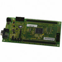
DEV EVALUATION KIT SH7145
Manufacturer
Renesas Electronics America
Type
MCUr
Datasheets
1.EDK7145.pdf
(19 pages)
2.EDK7145.pdf
(4 pages)
3.EDK7145.pdf
(5 pages)
4.EDK7145.pdf
(22 pages)
Specifications of EDK7145
Contents
2G (Second-generation) Evaluation Board, HEW debugger support, Cable and CD-ROM
Lead Free Status / RoHS Status
Contains lead / RoHS non-compliant
For Use With/related Products
SH7145
Lead Free Status / RoHS Status
Not Compliant, Contains lead / RoHS non-compliant


To enable the use of this alternate port the user must change the settings to those in the following table.
The user may implement a handshaking protocol on the EDK. This is not supported with the software tools supplied. To
support this option two spare port pins have been allocated on the microcontroller. Using these port pins the CTS and RTS
lines of the host serial interface can be controlled.
The user may also control the operation of the board via the same handshaking lines. This is not supported with the software
tools supplied but may be written by the user. Using the CTS line the user may simulate pressing the boot button, see
section:5.7. This will cause the EDK to swap into and out of Boot mode on each low-level activation of CTS. Feedback of the
current mode is provided on the RTS line. A high level indicates boot mode and a low level indicates user mode.
The following settings are made by default, and ensure that there are no conflicts on unnecessary microcontroller pins.
* See section 5.7
Note:
5.5. F
The Flash Programming header is used with the Hitachi Flash Development Module (FDM). The FDM is a USB based
programming tool for control and programming of Hitachi microcontrollers, available separately from Hitachi. This header
provides direct access for the FDM to control the EDK microcontroller.
To utilise this header the user must make the following changes to the board configuration.
1.
2.
Caution: Do not operate the board with the user mode jumpers removed and the FDM disconnected as the
microcontroller mode pins will float to an indeterminate state. This may damage the microcontroller device.
5.6. E
The External debug header may be used with the Hitachi E10A Debugger or a third party debugger.
The E10A is an on-chip debug emulator available separately from Hitachi.
This header provides direct access for the debugger to control the EDK microcontroller.
To utilise this header the user must enable the E10A interface via jumper CJ4-C. Please refer to section 5.3.
5.7. B
The method for placing the microcontroller device in to Boot mode for reprogramming has been incorporated into a complex
programmable logic device (CPLD). This is not necessary for most user designs but allows a measure of increased flexibility
for the EDK designs. Mode transitions including boot mode transitions only require the reset to be held active while the mode
settings are presented. On releasing reset the microcontroller will be in the required mode.
The logic design detects a power up event and provides a timed reset pulse to guarantee the reset of the device. At the end
of the rest pulse the processor will be placed in user mode and any code in the device will execute.
Disable the RX232 signal from the RS232 transceiver.
Jumper link CJ4-A is provided for this purpose. Please refer to section 5.3.
Disable User Program Mode using jumper CJ4-B. Please refer to section 5.3.
LASH
XTERNAL
These setting pairs are exclusive:
If CR12 and CR7 are fitted; CR16 and CR13 must not be fitted.
If CR16 and CR13 are fitted; CR12 and CR7 must not be fitted.
OOT
C
CR12
CR7
CR16
CR13
P
Zero-ohm
ONTROL
CR20
CR23
CR19
CR22
Link ID
ROGRAMMING
Zero-ohm
Link ID
D
EBUG
H
Not Fitted
Not Fitted
Not Fitted
Not Fitted
EADER
Default
Not Fitted
Not Fitted
Fitted
Fitted
H
Default
EADER
Mode State out from EDK
Change Mode request to EDK
Alternate RTS232 – Ready to send – from EDK
Alternate CTS232 – Clear to send – to EDK
T
T
Transmit data from EDK
Receive data to EDK
Alternate Transmit data from EDK
Alternate Receive data to EDK
ABLE
ABLE
5-4: O
5-5: O
PTION
PTION
L
Function
L
INKS
INKS
Function
– A
– S
LTERNATE
ERIAL
P
ORT
S
ERIAL
C
ONTROL
P
ORT
N/A (From CPLD*)
N/A (From CPLD*)
PA20
PB4
PA4
PA3
PA1
PA0
Microcontroller
Microcontroller
Port Pin
Port Pin
11
Related parts for EDK7145
Image
Part Number
Description
Manufacturer
Datasheet
Request
R

Part Number:
Description:
KIT STARTER FOR M16C/29
Manufacturer:
Renesas Electronics America
Datasheet:

Part Number:
Description:
KIT STARTER FOR R8C/2D
Manufacturer:
Renesas Electronics America
Datasheet:

Part Number:
Description:
R0K33062P STARTER KIT
Manufacturer:
Renesas Electronics America
Datasheet:

Part Number:
Description:
KIT STARTER FOR R8C/23 E8A
Manufacturer:
Renesas Electronics America
Datasheet:

Part Number:
Description:
KIT STARTER FOR R8C/25
Manufacturer:
Renesas Electronics America
Datasheet:

Part Number:
Description:
KIT STARTER H8S2456 SHARPE DSPLY
Manufacturer:
Renesas Electronics America
Datasheet:

Part Number:
Description:
KIT STARTER FOR R8C38C
Manufacturer:
Renesas Electronics America
Datasheet:

Part Number:
Description:
KIT STARTER FOR R8C35C
Manufacturer:
Renesas Electronics America
Datasheet:

Part Number:
Description:
KIT STARTER FOR R8CL3AC+LCD APPS
Manufacturer:
Renesas Electronics America
Datasheet:
Part Number:
Description:
KIT STARTER FOR RX610
Manufacturer:
Renesas Electronics America
Datasheet:

Part Number:
Description:
KIT STARTER FOR R32C/118
Manufacturer:
Renesas Electronics America
Datasheet:

Part Number:
Description:
KIT DEV RSK-R8C/26-29
Manufacturer:
Renesas Electronics America
Datasheet:

Part Number:
Description:
KIT STARTER FOR SH7124
Manufacturer:
Renesas Electronics America
Datasheet:

Part Number:
Description:
KIT STARTER FOR H8SX/1622
Manufacturer:
Renesas Electronics America
Datasheet:

Part Number:
Description:
KIT DEV FOR SH7203
Manufacturer:
Renesas Electronics America
Datasheet: