45300 Parallax Inc, 45300 Datasheet - Page 175
45300
Manufacturer Part Number
45300
Description
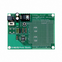
BOARD PROTO SX48
Manufacturer
Parallax Inc
Type
MCUr
Specifications of 45300
Contents
Board
Lead Free Status / RoHS Status
Contains lead / RoHS non-compliant
For Use With/related Products
SX48
For Use With
130-28029 - KIT PARTS SMART SENSORS45111 - MANUAL FOR SX-KEY/BLITZ VER. 2.028850 - CARRIER BOARD BOARD OF EDU USB
Lead Free Status / RoHS Status
Lead free / RoHS Compliant, Contains lead / RoHS non-compliant
Available stocks
Company
Part Number
Manufacturer
Quantity
Price

Part Number:
453001
Manufacturer:
LITTELFUSE/力特
Quantity:
20 000
Company:
Part Number:
453002
Manufacturer:
LITTELFU
Quantity:
1 000


15 Appendix E: SX Data Sheet
device directives in your source code to specify the bits in the Fuses register. See “Device Directive” in
Chapter 7.3.1 for additional information.
15.5 Interrupts
15.5.1 Description
Sometimes a particular task or event must have the immediate attention of the processor. An interrupt
is a means to accomplish this. In theory, the processor stops whatever it was doing and immediately
begins executing code located at a special location called the Interrupt Vector. Once the code located at
the Interrupt Vector task has completed, the processor returns to where it was before the interruption
occurred.
In reality, several things must occur in addition to the aforementioned to ensure proper operation of the
interrupt and the rest of the program. For one thing, consider the likely possibility that the interrupt
occurred when the W register held a number the main program was using for a calculation. More than
likely, the interrupt service routine will use the W register for its purposes too. When the processor
finishes the interrupt service routine and returns to what it was doing before, the W register will hold a
different value than what it held before the interrupt occurred. This can lead to bizarre program execu-
tion. In addition to the W register, the Status and FSR registers must be ‘preserved’ across an interrupt.
Traditionally, these issues were dealt with by software within the interrupt service routine. The
engineers at Ubicom had the foresight to take the burden off the programmer and put it in the chip
where it belongs.
15.5.2 The Specifics
When an interrupt occurs in an SX chip, the PC, STATUS, FSR, and W registers are saved in special
shadow locations, and additional interrupts ignored. The program counter is loaded with $00, (The
Interrupt Vector), and the top three bits of the STATUS register, (PA2:PA0) are cleared to $0. When the
interrupt service routine has completed and the ‘RETI’ instruction is executed, the PC, STATUS, FSR,
and W registers are restored and the interrupt is re-enabled. Since this occurs automatically, your
interrupt service routine does not have to waste any valuable time copying several registers back and
forth.
15.5.3 RTCC Interrupt
The SX chip offers one internal interrupt called the RTCC rollover. If enabled, when the RTCC
increments from $FF to $00, an interrupt will be generated. The latency, or response delay, will be
exactly three instruction cycles in Turbo Mode, and exactly eight cycles in Non-Turbo mode. When the
interrupt is complete, there will be a three-cycle delay (Turbo mode) or an eight-cycle delay (Non-Turbo
mode) before main code begins executing. This is due to the pipeline. Whenever an instruction is
executed and, because of the instruction, the program counter is changed, the pipeline must be flushed
and refilled. See “RTCC Rollover Interrupts” in Chapter 10.4.1 for more information.
SX-Key/Blitz Development System Manual 2.0 Parallax, Inc. Page 175
Related parts for 45300
Image
Part Number
Description
Manufacturer
Datasheet
Request
R


Part Number:
Description:
Microcontroller Modules & Accessories DISCONTINUED BY PARALLAX
Manufacturer:
Parallax Inc

Part Number:
Description:
BOOK UNDERSTANDING SIGNALS
Manufacturer:
Parallax Inc
Datasheet:


Part Number:
Description:
COMPETITION RING FOR SUMOBOT
Manufacturer:
Parallax Inc
Datasheet:


Part Number:
Description:
TEXT INFRARED REMOTE FOR BOE-BOT
Manufacturer:
Parallax Inc
Datasheet:
Part Number:
Description:
BOARD EXPERIMENT+LCD NX-1000
Manufacturer:
Parallax Inc
Datasheet:

Part Number:
Description:
CONTROLLER 16SERVO MOTOR CONTROL
Manufacturer:
Parallax Inc
Datasheet:

Part Number:
Description:
BASIC STAMP LOGIC ANALYZER
Manufacturer:
Parallax Inc
Datasheet:

Part Number:
Description:
IC MCU 2K FLASH 50MHZ SO-18
Manufacturer:
Parallax Inc
Datasheet: