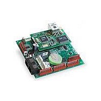
101-0577 Rabbit Semiconductor, 101-0577 Datasheet - Page 47

101-0577
Manufacturer Part Number
101-0577
Description
KIT DEV FOR BL2500 COYOTE
Manufacturer
Rabbit Semiconductor
Series
Coyoter
Type
Single Board Computers (SBC)r
Datasheet
1.101-0576.pdf
(106 pages)
Specifications of 101-0577
Contents
SBC, Dev. Board, AC Adapter, Cable and Dynamic C® CD-ROM
Product
Modules
Data Bus Width
10 bit
Processor Type
Rabbit 3000
Sram
128 KB
Flash
256 KB
Number Of I/os
24
Backup Battery
3 V Lithium Coin Type
Operating Voltage
8 V to 40 V
Power Consumption
1 W
Board Size
100 mm x 100 mm x 29 mm
Description/function
Computer Module
Interface Type
Ethernet
For Use With/related Products
BL2510
Lead Free Status / RoHS Status
Contains lead / RoHS non-compliant
4.2 Sample Programs
Sample programs are provided in the Dynamic C
PONG.C
SAMPLES
ing Dynamic C libraries.
The
sample program has comments that describe the purpose and function of the program. Fol-
low the instructions at the beginning of the sample program.
To run a sample program, open it with the
the
in Program mode (see Section 3.6, “Serial Programming Cable”) and must be connected
to a PC using the programming cable as described in Section 2.2, “BL2500 Connections.”
More complete information on Dynamic C is provided in the Dynamic C User’s Manual.
4.2.1 General Coyote Operation
The following sample programs are found in the
•
•
•
4.2.2 Digital I/O
The following sample programs are found in the
•
•
4.2.3 Serial Communication
The following sample programs are found in the
•
User’s Manual
CONTROLLED.C
Demonstration Board.
FLASHLEDS.C
different intervals.
TOGGLESWITCH.C
tion Board with press and release debouncing. Corresponding LEDs will turn on or off.
DIGIN.C
call
HIGH to LOW when pressing a pushbutton on the Demonstration Board.
DIGOUT.C
call
nels in the
tion Board.
FLOWCONTROL.C
characters out of Serial Port E (PG6) at115,200 bps. One character at a time is received
from PG6 and is displayed. In this example, PG3 is configured as the CTS input,
detecting a clear to send condition, and PG2 is configured as the RTS output, signaling
a ready condition. This demonstration can be performed with either one or two boards.
Compile
SAMPLES\BL2500
digIn()
digOut()
demonstrates the output to the
folder contain specific sample programs that illustrate the use of the correspond-
—This program demonstrates the use of the digital inputs and the function
menu, and then run it by selecting
—This program demonstrates the use of the digital outputs and the function
STDIO
using the Demonstration Board to see an input channel toggle from
—Uses cofunctions and costatements to flash LEDs on the Coyote at
using the Demonstration Board to see the logic levels of output chan-
—Uses the D/A converters to vary the brightness of the LEDs on the
—Demonstrates hardware flow control by sending a pattern of *
window and the state of the corresponding LEDs on the Demonstra-
—Uses costatements to detect switches presses on the Demonstra-
folder provides sample programs specific to the Coyote. Each
STDIO
File
menu (if it is not still open), compile it using
Run
SERIAL
window. The various directories in the
SAMPLES\BL2500
IO
SAMPLES
in the
subdirectory in
subdirectory in
Run
folder. The sample program
menu. The Coyote must be
SAMPLES\BL2500
.
SAMPLES\BL2500
.
41
.


