DC-EM-KT Digi International, DC-EM-KT Datasheet - Page 91
DC-EM-KT
Manufacturer Part Number
DC-EM-KT
Description
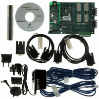
KIT INTEGRATION EM FOR S MODELS
Manufacturer
Digi International
Series
Digi Connect EM®r
Type
MCU Moduler
Specifications of DC-EM-KT
Contents
Module with plug-and-play firmware, Development Board, Documentation, CD, Cables and Power Supply
For Use With/related Products
Digi Connect EM S Module
Lead Free Status / RoHS Status
Contains lead / RoHS non-compliant
Other names
602-1003
DC-EM-01T-KT
DC-EM-02T-KT
DC-EM-01T-KT
DC-EM-02T-KT


Additional Implementation Required for Input and Output Choices
Changing the GPIO pin settings from Serial to Input or Output means that you are
completely responsible for implementing how the pins and signals will work, including
developing any applications, signal-handling, and hardware.
Serial: The GPIO pin is used for standard serial communication signalling.
Each pin maps to a different serial signal as listed in parentheses next to the pin.
(DCD, CTS, DSR, ...). This is the default setting for all GPIO pins. The default
serial settings for the GPIO pins on a Digi Connect device are as follows.
Depending on the device, there are five or nine pins.
In: The GPIO pin is used for user-defined signal input from the connected
device to the Digi Connect device. An email notification can be sent when an
input event is signalled, as discussed in "Configure Alarms" on page 93.
Out: The GPIO pin is used for user-defined signal output from the Digi
Connect device to the connected device.
Pin Number
GPIO 1
GPIO 2
GPIO 3
GPIO 4
GPIO 5
GPIO 6
GPIO 7
GPIO 8
GPIO 9
Default Serial Signal
TXD for port 2
RXD for port 2
DCD
DTR
TXD
RXD
DSR
CTS
RTS
C o n f i g u r i n g t h e D i g i C o n n e c t D e v i c e s
Signal Direction
Output
Output
Output
Output
Input
Input
Input
Input
Input
9 1
Related parts for DC-EM-KT
Image
Part Number
Description
Manufacturer
Datasheet
Request
R

Part Number:
Description:
KIT DEV EM MOD NO RAVEN DEBUG
Manufacturer:
Digi International
Datasheet:

Part Number:
Description:
KIT JUMP START EM FOR NET+OS 7.X
Manufacturer:
Digi International
Datasheet:
Part Number:
Description:
KIT DEV EM MODULE C MODELS
Manufacturer:
Digi International
Datasheet:
Part Number:
Description:
BOARD DEV EM MODULE JTAG WI-ME
Manufacturer:
Digi International
Datasheet:

Part Number:
Description:
EM 8MB SDRAM 4MB FLASH SINGLE
Manufacturer:
Digi International
Datasheet:

Part Number:
Description:
EM 8MB SDRAM 4MB FLASH SINGLE
Manufacturer:
Digi International
Datasheet:
Part Number:
Description:
EM 8MB SDRAM 4MB FLASH SINGLE
Manufacturer:
Digi International
Part Number:
Description:
EM 8MB SDRAM 4MB FLASH SINGLE
Manufacturer:
Digi International
Datasheet:
Part Number:
Description:
EM 8MB SDRAM 4MB FLASH 25 PAK
Manufacturer:
Digi International
Part Number:
Description:
EM 8MB SDRAM 4MB FLASH 25 PAK
Manufacturer:
Digi International
Part Number:
Description:
EM 8MB SDRAM 4MB FLASH 25 PAK
Manufacturer:
Digi International
Part Number:
Description:
EM 8MB SDRAM 4MB FLASH SINGLE
Manufacturer:
Digi International

Part Number:
Description:
Networking Modules & Development Tools EM Intergration Kit for S Modules
Manufacturer:
Digi International
Datasheet:
Part Number:
Description:
KIT INTEGRATION WI-EM S MODELS
Manufacturer:
Digi International
Datasheet: