DC-EM-KT Digi International, DC-EM-KT Datasheet - Page 26
DC-EM-KT
Manufacturer Part Number
DC-EM-KT
Description
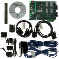
KIT INTEGRATION EM FOR S MODELS
Manufacturer
Digi International
Series
Digi Connect EM®r
Type
MCU Moduler
Specifications of DC-EM-KT
Contents
Module with plug-and-play firmware, Development Board, Documentation, CD, Cables and Power Supply
For Use With/related Products
Digi Connect EM S Module
Lead Free Status / RoHS Status
Contains lead / RoHS non-compliant
Other names
602-1003
DC-EM-01T-KT
DC-EM-02T-KT
DC-EM-01T-KT
DC-EM-02T-KT


2 6
F e a t u r e s
The configuration and current state of GPIO pins can be easily viewed, through the Web
user interface or by issuing commands from the command line.
DHCP Server
The Digi Connect WAN device is running a DHCP server. The DHCP server is enabled by
default but can be disabled in the setup wizard. Configure the setup device to obtain IP
adresses automatically. This eliminates subnet errors.
Power Requirements
The power requirements for Digi Connect devices are as follows. See also the Hardware
Reference for your Digi Connect device for additional information.
Power Requirements Digi Connect SP Digi Connect Wi-SP, Digi Connect WAN, and
Digi Connect RG
The Digi Connect SP, Digi Connect Wi-SP, Digi Connect WAN, and Digi Connect RG
must be powered by a Listed LPS or Class II power supply rated 9-30 VDC, 0.37 A
minimum. The power supply shipped with the Digi Connect WAN provides surge
protection covering 4Kv burst (EFT) per -4-4 and 2Kv surge per EN61000-4-5 (non-
condensing). See the Hardware Reference or the Quick Start guide for your Digi Connect
device for additional information.
DC Characteristics for Embedded Devices
Digi Connect ME, Digi Connect Wi-ME, Digi Connect EM, and Digi Connect Wi-EM
The following tables list DC characteristics for operating conditions, inputs, and outputs
for Digi Connect ME, Digi Connect Wi-ME, Dig Connect EM, and Digi Connect Wi-EM
devices.
Serial mode allows normal serial operation.
Input mode allows input of GPIO signals. Alarms can be issued when GPIO
pins change state. Input mode is used in conjunction with alarms to trigger
emails or SNMP traps when a particular signal change is detected (see
"Alarms" on page 39).
Output mode allows output of GPIO signals. This mode can be used to toggle
the output of GPIO signals between high and low.
D i g i C o n n e c t F a m i l y U s e r ’ s G u i d e
Related parts for DC-EM-KT
Image
Part Number
Description
Manufacturer
Datasheet
Request
R

Part Number:
Description:
KIT DEV EM MOD NO RAVEN DEBUG
Manufacturer:
Digi International
Datasheet:

Part Number:
Description:
KIT JUMP START EM FOR NET+OS 7.X
Manufacturer:
Digi International
Datasheet:
Part Number:
Description:
KIT DEV EM MODULE C MODELS
Manufacturer:
Digi International
Datasheet:
Part Number:
Description:
BOARD DEV EM MODULE JTAG WI-ME
Manufacturer:
Digi International
Datasheet:

Part Number:
Description:
EM 8MB SDRAM 4MB FLASH SINGLE
Manufacturer:
Digi International
Datasheet:

Part Number:
Description:
EM 8MB SDRAM 4MB FLASH SINGLE
Manufacturer:
Digi International
Datasheet:
Part Number:
Description:
EM 8MB SDRAM 4MB FLASH SINGLE
Manufacturer:
Digi International
Part Number:
Description:
EM 8MB SDRAM 4MB FLASH SINGLE
Manufacturer:
Digi International
Datasheet:
Part Number:
Description:
EM 8MB SDRAM 4MB FLASH 25 PAK
Manufacturer:
Digi International
Part Number:
Description:
EM 8MB SDRAM 4MB FLASH 25 PAK
Manufacturer:
Digi International
Part Number:
Description:
EM 8MB SDRAM 4MB FLASH 25 PAK
Manufacturer:
Digi International
Part Number:
Description:
EM 8MB SDRAM 4MB FLASH SINGLE
Manufacturer:
Digi International

Part Number:
Description:
Networking Modules & Development Tools EM Intergration Kit for S Modules
Manufacturer:
Digi International
Datasheet:
Part Number:
Description:
KIT INTEGRATION WI-EM S MODELS
Manufacturer:
Digi International
Datasheet: