101-0359 Rabbit Semiconductor, 101-0359 Datasheet - Page 26
101-0359
Manufacturer Part Number
101-0359
Description
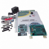
KIT DEVELOPMENT BASIC RABBIT2000
Manufacturer
Rabbit Semiconductor
Series
RabbitCore 2000r
Type
MPU Moduler
Datasheet
1.101-0359.pdf
(54 pages)
Specifications of 101-0359
Rohs Status
RoHS non-compliant
Contents
RabbitCore Module, Dev. Board, AC Adapter, Cable and Dynamic C® CD-Rom
Processor To Be Evaluated
Rabbit 2000
Interface Type
RS-232, RS-485
For Use With/related Products
RCM2000, RCM2010, RCM2020
Lead Free Status / Rohs Status
Lead free / RoHS Compliant
Other names
316-1003


3.1.1 Other Sample Programs Illustrating Digital I/O
•
•
•
•
Before running the
install 3 mm LEDs such as the Vishay Telefunken TLUR4400 at DS5–DS8 on the Jack-
rabbit Prototyping Board. These LEDs are included with the Rabbit 2000 Development Kit.
•
•
22
DEMOJR2.C
typing Board.
This sample program also illustrates the use of the
Dynamic C to update watch expressions while running. To test this:
DEMOJR3.C
by PA3) on the Prototyping Board. This sample program will also watch button S1
(PB2) and toggle LED DS1 (which is controlled by PA0) on/off when pressed. Note
that S1 presses are debounced by the software.
Parallel Port A can be set for all outputs or all inputs via the slave port control register
(SPCTR). Do not use Parallel Port A if the slave port is being used.
Bits 0–5 on Parallel Port B are always inputs, and bits 6–7 are always outputs. Do not
use Parallel Port B if the slave port is being used.
JRIOTEST.C
input channel, and the two analog output channels.
JRIO_COF.C
Before you run this sample program, connect DA1 to AD0 on header J7 of the Proto-
typing Board to provide an input voltage. Once the sample program is running, it will
read the input voltage ten times while another costatement is executed concurrently. The
values will be printed out in the Dynamic C
RABDB01.C
to PA4–PA7) when corresponding switches S1–S4 (which are connected to PB2–PB5)
are pressed. The buzzer, which is driven by HV0 from PE0, will also sound whenever
switch S1 switch is pressed.
RABDB02.C
to PA4–PA7) when corresponding switches S1–S4 (which are connected to PB2–PB5)
are pressed. The buzzer, which is driven by HV0 from PE0, will also sound whenever
switch S1 switch is pressed.
1. Add a watch expression for "k" under "Inspect:Add/Del Watch Expression."
2. Click "Add to top" so that it will be permanently in the watch list.
3. While the program is running, type
—repeatedly flashes LED DS3 (which is controlled by PA2) on the Proto-
—demonstrates the use of costatements to LED DS4 (which is controlled
—flashes LEDs DS5–DS8 on the Prototyping Board (which are connected
—flashes LEDs DS5–DS8 on the Prototyping Board (which are connected
—exercises the BL1810's four digital output channels, the one analog
—demonstrates the use of cofunctions with the analog input driver.
RABDB01.C
and the
RABDB02.C
<Ctrl+U>
STDIO
sample programs, you will need to
to update the watch window.
runwatch()
window at the end of the program.
Rabbit 2000 Development Kit
function to allow
Related parts for 101-0359
Image
Part Number
Description
Manufacturer
Datasheet
Request
R

Part Number:
Description:
COMPUTER SNGLBD BL2101 A/D 0-10V
Manufacturer:
Rabbit Semiconductor
Part Number:
Description:
CARD D/A 0-10V SR9400 SMARTSTAR
Manufacturer:
Rabbit Semiconductor
Datasheet:
Part Number:
Description:
CARD A/D 0-10V SR9300 SMARTSTAR
Manufacturer:
Rabbit Semiconductor
Datasheet:

Part Number:
Description:
WiFi / 802.11 Modules & Development Tools WIRELESS CONTROL APP KIT
Manufacturer:
Rabbit Semiconductor

Part Number:
Description:
KIT DEV RABBITCORE RCM3750
Manufacturer:
Rabbit Semiconductor
Datasheet:
Part Number:
Description:
KIT DEV RABBIT 2000 INT'L
Manufacturer:
Rabbit Semiconductor
Datasheet:
Part Number:
Description:
KIT DEV RABBIT RCM2000 INT'L
Manufacturer:
Rabbit Semiconductor
Datasheet:

Part Number:
Description:
KIT DEVELOPMENT RCM3700 INT'L
Manufacturer:
Rabbit Semiconductor
Datasheet:

Part Number:
Description:
BL4S200 TOOL KIT
Manufacturer:
Rabbit Semiconductor
Datasheet:
Part Number:
Description:
MODULE RABBITCORE RCM3720
Manufacturer:
Rabbit Semiconductor
Datasheet:
Part Number:
Description:
MODULE RABBITCORE RCM3220
Manufacturer:
Rabbit Semiconductor
Datasheet:
Part Number:
Description:
MODULE RABBITCORE RCM3210
Manufacturer:
Rabbit Semiconductor
Datasheet:
Part Number:
Description:
COMPUTER SGL-BOARD OP6600 W/SRAM
Manufacturer:
Rabbit Semiconductor
Datasheet:
Part Number:
Description:
COMPUTER SGL-BD BL2000 SRAM/FLSH
Manufacturer:
Rabbit Semiconductor