MPC8313E-RDB Freescale Semiconductor, MPC8313E-RDB Datasheet - Page 44
MPC8313E-RDB
Manufacturer Part Number
MPC8313E-RDB
Description
BOARD PROCESSOR
Manufacturer
Freescale Semiconductor
Series
PowerQUICC II™ PROr
Type
MCUr
Datasheets
1.MPC8313CZQAFFB.pdf
(100 pages)
2.MPC8313E-RDBB.pdf
(52 pages)
3.MPC8313E-RDBB.pdf
(2 pages)
Specifications of MPC8313E-RDB
Contents
Reference Design Board, Software and Documentation
Termination Type
SMD
Supply Voltage Max
1.05V
Tool / Board Applications
Wired Connectivity-LIN, CAN, Ethernet, USB
Mcu Supported Families
POWERQUICC II PRO
Rohs Compliant
Yes
Filter Terminals
SMD
Silicon Manufacturer
Freescale
Silicon Core Number
MPC83xx
Kit Application Type
Communication & Networking
Application Sub Type
Ethernet
Core Architecture
Power Architecture
Silicon Family Name
PowerQUICC II PRO
For Use With/related Products
MPC8313E
Lead Free Status / RoHS Status
Lead free / RoHS Compliant


Getting Started
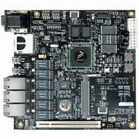
6.1
Figure 41
DIP switches (S3, S4) and one jumper (J19). Their default settings are listed in
44
Board Jumper Settings
shows the top view of the MPC8313E RDB with pin 1 marked for each reference. There are two
Pin 1
J20
PowerQUICC™ MPC8313E Reference Design Board (RDB), Rev. 4
Power On
Button,
Reset Button
MPC8313E-RDB
S/N:
J19
Reference
PCI Slot [IDSEL-AD15]
Micro-jumper/resistor option area
for RGMII/ULPI/IEEE1588 selection
and L2 Switch/PHY selection
MCU
Connector
Table 23. Default DIP Switch and Jumper Setting
S2
S1
J24
J19
S3
S4
D22
D3
J21
D21
D5 D2 D1
Programmable
LED0-7
Figure 41. MPC8313E-RDB Top View
D20
LCD Connector
LCD Connector
D4
J22
P2
LCD Backlight
J23
MPC8313E
open (no jumper)
Default Setting
1111 (all OFF)
miniPCI Slot [IDSEL-AD14]
P3
0000 (all ON)
P10
IEEE 1588 Connector (Optional)
D16
D15
D14
D17
D13
COP Connector
ON
1
P1
2
S4
3
4
VBUS
CTL0
CTL1
ON
1
S3
2
U44
3
P5
P6
D12
D10
D11
P7
4
Table
D6
D7
D8
D9
P11
Freescale Semiconductor
23.
P4
P8
Related parts for MPC8313E-RDB
Image
Part Number
Description
Manufacturer
Datasheet
Request
R

Part Number:
Description:
Mpc8313e Powerquicc Ii Pro Processor
Manufacturer:
Freescale Semiconductor, Inc
Datasheet:

Part Number:
Description:
BOARD CPU 8313E VER 2.1
Manufacturer:
Freescale Semiconductor
Datasheet:

Part Number:
Description:
BOARD CPU 8313E VER 2.2
Manufacturer:
Freescale Semiconductor
Datasheet:
Part Number:
Description:
Microprocessors - MPU 8313 REV2.2 PB ENC EXT
Manufacturer:
Freescale Semiconductor
Datasheet:
Part Number:
Description:
Microprocessors - MPU 8313 REV2.2 PB W/ENC
Manufacturer:
Freescale Semiconductor
Datasheet:
Part Number:
Description:
Microprocessors - MPU 8313 REV2.2 PB NO EN EXT
Manufacturer:
Freescale Semiconductor
Datasheet:
Part Number:
Description:
Microprocessors - MPU 8313 REV2.2 PB NO ENC
Manufacturer:
Freescale Semiconductor
Datasheet:
Part Number:
Description:
Manufacturer:
Freescale Semiconductor, Inc
Datasheet:
Part Number:
Description:
Manufacturer:
Freescale Semiconductor, Inc
Datasheet:
Part Number:
Description:
Manufacturer:
Freescale Semiconductor, Inc
Datasheet:
Part Number:
Description:
Manufacturer:
Freescale Semiconductor, Inc
Datasheet:
Part Number:
Description:
Manufacturer:
Freescale Semiconductor, Inc
Datasheet:
Part Number:
Description:
Manufacturer:
Freescale Semiconductor, Inc
Datasheet:
Part Number:
Description:
Manufacturer:
Freescale Semiconductor, Inc
Datasheet:
Part Number:
Description:
Manufacturer:
Freescale Semiconductor, Inc
Datasheet: