M68EVB908QL4 Freescale Semiconductor, M68EVB908QL4 Datasheet
M68EVB908QL4
Specifications of M68EVB908QL4


Related parts for M68EVB908QL4

M68EVB908QL4 Summary of contents
Page 1
... M68EVB908QL4 Development Board for Motorola MC68HC908QL4 ! Axiom Manufacturing • 2813 Industrial Lane • Garland, TX 75041 Email: Sales@axman.com ! Web: http://www.axman.com ...
Page 2
... CAUTIONARY NOTES ...........................................................................................................................................................3 TERMINOLOGY ......................................................................................................................................................................3 FEATURES................................................................................................................................................................................4 GETTING STARTED............................................................................................................................................................... .................................................................................................................................................5 EFERENCE OCUMENTATION M68EVB908QL4 S .....................................................................................................................................................6 TARTUP M68EVB908QL4 OPERATION ..............................................................................................................................................6 MEMORY MAP......................................................................................................................................................................6 POWER SUPPLY ...................................................................................................................................................................7 PWR_SEL Option ................................................................................................................................................................7 +5V_EN Option...................................................................................................................................................................7 POWER Indicator................................................................................................................................................................7 PWR - Power Jack ............................................................................................................................................................... ...............................................................................................................................................................7 AND OCKETS USER_COMPONENTS ..........................................................................................................................................................8 JP1 USER OPTIONS...........................................................................................................................................................8 RESET Switch ......................................................................................................................................................................8 IRQ Switch ...........................................................................................................................................................................8 RV1 User Potentiometer ......................................................................................................................................................8 MON08 DEBUG PORT ..........................................................................................................................................................9 MON_EN Option ...
Page 3
... EMC Information on the M68EVB908QL4 board: a) This product as shipped from the factory with associated power supplies and cables, has been tested and meets with requirements of CE and the FCC as a CLASS A product. ...
Page 4
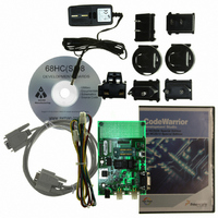
... FEATURES The M68EVB908QL4 is an evaluation or development board for the MC68HC908QL4 microcontroller. Development of applications is quick and easy with the included DB9 serial cable, sample software tools, examples, and debug monitor MON08. The prototyping area provides space to apply the CPU I/O to your needs. The Cyclone port is provided for high-end development tool application ...
Page 5
... GETTING STARTED The M68EVB908QL4 single board computer is a fully assembled, fully functional development board for the Motorola MC68HC908QL4 microcontroller. Provided with wall plug power supply and serial cable. Support software for this development board is provided for Windows 95/98/NT/2000/XP operating systems. Development board users should also be familiar with the hardware and software operation of the target HC08 device, refer to the provided Motorola User Guide for the device and the HC08 Reference Manual for details ...
Page 6
... Install MON08 hosting software for applying the DEBUG port on the host PC. 4) Connect the M68EVB908QL4 board DEBUG serial connector to the host PC COM port with the provided serial cable. 5) Launch the host MON08 software and mass or bulk erase the QL4 flash to unsecure the device flash ...
Page 7
POWER SUPPLY Input power is applied by external connection to the PWR power jack or LIN-J1/2 port connectors. The input source is selected by the PWR_SEL option jumper. ...
Page 8
USER_COMPONENTS Two push switches, potentiometer, and LED indicator are provided for user application. JP1 USER OPTIONS The JP1 option block provides a method to enable or connect user ...
Page 9
... BREAK or RESET. Hosting software is required to communicate with the monitor on this port. Do not apply the DEBUG port and CYCLONE cable at the same time. Refer to the M68EVB908QL4 schematic drawing for circuit and connector connections. MON_EN Option The MON_EN 1 and 2 option jumpers provide HC08 MON08 signals to the DEBUG Port. ...
Page 10
LIN- PORTS The LIN ports provide parallel connectors for attaching a LIN network. Providing two connectors enables the user to either connect additional slave nodes or ...
Page 11
LIN Connectors and Options The LIN network connectors (LIN-J1 and LIN-J2) provide a standard pin configuration with a network option position. Front view (looking into connector from outside ...
Page 12
... N connection TROUBLESHOOTING The M68EVB908QL4 is fully tested and operational before shipping fails to function properly, inspect the board for obvious physical damage first. Verify the setup as described under GETTING STARTED and START-UP sections of this manual. 1. Verify proper installation of a MC68HC908QL4 in the socket (not both). ...
Page 13
... M68EVB908QL4 Schematic Errata M68EVB908QL4 (AXM0323) Revision D: 1) PTA1 has a 100K pull-up resistor to +5V to provide DEBUG port Monitor mode entry. Not shown on Rev D schematic. 2) PTA4 has a 100K pull-down resistor to Ground/VSS to provide DEBUG port Monitor mode entry. Not shown on Rev D schematic ...