C8051T610DK Silicon Laboratories Inc, C8051T610DK Datasheet - Page 198
C8051T610DK
Manufacturer Part Number
C8051T610DK
Description
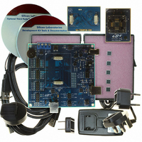
KIT DEV FOR C8051T61X MCU'S
Manufacturer
Silicon Laboratories Inc
Type
MCUr
Specifications of C8051T610DK
Contents
Board, daughter boards, power adapter, cables, documentation and software
Processor To Be Evaluated
C8051T61x
Interface Type
USB
Lead Free Status / RoHS Status
Lead free / RoHS Compliant
For Use With/related Products
C8051T610
For Use With
336-1507 - DAUGHTER BOARD T610 24QFN SOCKET336-1506 - DAUGHTER BOARD T610 28QFN SOCKET336-1505 - DAUGHT BOARD T610 32TQFP SOCKET
Lead Free Status / Rohs Status
Lead free / RoHS Compliant
Other names
336-1443


C8051T610/1/2/3/4/5/6/7
26.3.5. 8-bit Pulse Width Modulator Mode
The duty cycle of the PWM output signal in 8-bit PWM mode is varied using the module's PCA0CPLn cap-
ture/compare register. When the value in the low byte of the PCA counter/timer (PCA0L) is equal to the
value in PCA0CPLn, the output on the CEXn pin will be set. When the count value in PCA0L overflows, the
CEXn output will be reset (see Figure 26.8). Also, when the counter/timer low byte (PCA0L) overflows from
0xFF to 0x00, PCA0CPLn is reloaded automatically with the value stored in the module’s capture/compare
high byte (PCA0CPHn) without software intervention. Setting the ECOMn and PWMn bits in the
PCA0CPMn register enables 8-Bit Pulse Width Modulator mode. If the MATn bit is set to 1, the CCFn flag
for the module will be set each time an 8-bit comparator match (rising edge) occurs. The duty cycle for 8-
Bit PWM Mode is given in Equation 26.2.
Important Note About Capture/Compare Registers: When writing a 16-bit value to the PCA0 Cap-
ture/Compare registers, the low byte should always be written first. Writing to PCA0CPLn clears the
ECOMn bit to 0; writing to PCA0CPHn sets ECOMn to 1.
Using Equation 26.2, the largest duty cycle is 100% (PCA0CPHn = 0), and the smallest duty cycle is
0.39% (PCA0CPHn = 0xFF). A 0% duty cycle may be generated by clearing the ECOMn bit to 0.
198
PCA0CPLn
Write to
Reset
PCA0CPHn
Write to
0
ENB
ENB
1
W
M
P
1
6
n
0
Figure 26.8. PCA 8-Bit PWM Mode Diagram
E
C
O
M
n
PCA0CPMn
C
A
P
P
n
0 0 x 0
C
A
P
N
n
Equation 26.2. 8-Bit PWM Duty Cycle
M
A
T
n
O
G
T
n
Duty Cycle
P
W
M
n
C
C
E
F
n
x
PCA Timebase
Enable
=
PCA0CPHn
Comparator
PCA0CPLn
-------------------------------------------------- -
Rev 1.0
PCA0L
256 PCA0CPHn
8-bit
–
256
Overflow
COVF
match
S
R
SET
CLR
Q
Q
CEXn
Crossbar
Port I/O
Related parts for C8051T610DK
Image
Part Number
Description
Manufacturer
Datasheet
Request
R

Part Number:
Description:
SMD/C°/SINGLE-ENDED OUTPUT SILICON OSCILLATOR
Manufacturer:
Silicon Laboratories Inc
Part Number:
Description:
Manufacturer:
Silicon Laboratories Inc
Datasheet:
Part Number:
Description:
N/A N/A/SI4010 AES KEYFOB DEMO WITH LCD RX
Manufacturer:
Silicon Laboratories Inc
Datasheet:
Part Number:
Description:
N/A N/A/SI4010 SIMPLIFIED KEY FOB DEMO WITH LED RX
Manufacturer:
Silicon Laboratories Inc
Datasheet:
Part Number:
Description:
N/A/-40 TO 85 OC/EZLINK MODULE; F930/4432 HIGH BAND (REV E/B1)
Manufacturer:
Silicon Laboratories Inc
Part Number:
Description:
EZLink Module; F930/4432 Low Band (rev e/B1)
Manufacturer:
Silicon Laboratories Inc
Part Number:
Description:
I°/4460 10 DBM RADIO TEST CARD 434 MHZ
Manufacturer:
Silicon Laboratories Inc
Part Number:
Description:
I°/4461 14 DBM RADIO TEST CARD 868 MHZ
Manufacturer:
Silicon Laboratories Inc
Part Number:
Description:
I°/4463 20 DBM RFSWITCH RADIO TEST CARD 460 MHZ
Manufacturer:
Silicon Laboratories Inc
Part Number:
Description:
I°/4463 20 DBM RADIO TEST CARD 868 MHZ
Manufacturer:
Silicon Laboratories Inc
Part Number:
Description:
I°/4463 27 DBM RADIO TEST CARD 868 MHZ
Manufacturer:
Silicon Laboratories Inc
Part Number:
Description:
I°/4463 SKYWORKS 30 DBM RADIO TEST CARD 915 MHZ
Manufacturer:
Silicon Laboratories Inc
Part Number:
Description:
N/A N/A/-40 TO 85 OC/4463 RFMD 30 DBM RADIO TEST CARD 915 MHZ
Manufacturer:
Silicon Laboratories Inc
Part Number:
Description:
I°/4463 20 DBM RADIO TEST CARD 169 MHZ
Manufacturer:
Silicon Laboratories Inc