C8051F336DK Silicon Laboratories Inc, C8051F336DK Datasheet - Page 6
C8051F336DK
Manufacturer Part Number
C8051F336DK
Description
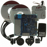
DEV KIT FOR C8051F336
Manufacturer
Silicon Laboratories Inc
Type
MCUr
Specifications of C8051F336DK
Contents
Evaluation Board, Power Supply, USB Cables, Adapter and Documentation
Processor To Be Evaluated
C8051F33x
Interface Type
USB, UART
Operating Supply Voltage
7 V to 15 V
Lead Free Status / RoHS Status
Lead free / RoHS Compliant
For Use With/related Products
C8051F336
Lead Free Status / Rohs Status
Lead free / RoHS Compliant
Other names
336-1430


C8051F336DK
6.2. Building and Downloading the Program for Debugging
7. Example Source Code
Example source code and register definition files are provided in the “SiLabs\MCU\Examples\C8051F336_9\”
directory during IDE installation. These files may be used as a template for code development. Example
applications include a blinking LED example which configures the green LED on the target board to blink at a fixed
rate.
7.1. Register Definition Files
Register definition files C8051F336.inc and C8051F336_defs.h define all SFR registers and bit-addressable
control/status bits. A macro definition header file compiler_defs.h is also included, and is required to be able to use
the
“SiLabs\MCU\Examples\C8051F336_9\Header_Files\” directory during IDE installation by default. The register and
bit names are identical to those used in the C8051F336/7/8/9 data sheet. These register definition files are also
installed in the default search path used by the Keil Software 8051 tools. Therefore, when using the Keil 8051 tools
included with the development kit (A51, C51), it is not necessary to copy a register definition file to each project’s
file directory.
7.2. Blinking LED Example
The
“SiLabs\MCU\Examples\C8051F336_9\Blinky” show examples of several basic C8051F338 functions. These
include disabling the watchdog timer (WDT), configuring the Port I/O crossbar, configuring a timer for an interrupt
routine, initializing the system clock, and configuring a GPIO port pin. When compiled/assembled and linked this
program flashes the green LED on the C8051F338 target board about five times a second using the interrupt
handler with a C8051F338 timer.
7.3. Touch Sensitive Switch Example
The example source file F338_TouchSense_Switch.c demonstrates the configuration and usage of the touch
sensitive (contactless) switch SW3. Refer to the source file for step-by-step instructions to build and test this
example. This is installed in the “SiLabs\MCU\Examples\C8051F336_9\TouchSense_Switch” directory by default.
6
1. Once all source files have been added to the target build, build the project by clicking on the Build/Make
2. Before connecting to the target device, several connection options may need to be set. Open the
3. Click the Connect button in the toolbar or select Debug
4. Download the project to the target by clicking the Download Code button in the toolbar.
5. Save the project when finished with the debug session to preserve the current target build configuration,
C8051F336_defs.h
example
Project button in the toolbar or selecting Project
Note: After the project has been built the first time, the Build/Make Project command will only build the
files that have been changed since the previous build. To rebuild all files and project dependencies, click
on the Rebuild All button in the toolbar or select Project
Connection Options window by selecting Options
the appropriate adapter in the “Serial Adapter” section. Next, the correct “Debug Interface” must be selected.
C8051F336/7/8/9 family devices use the Silicon Labs 2-wire (C2) debug interface. Once all the selections are
made, click the OK button to close the window.
Note: To enable automatic downloading if the program build is successful select Enable automatic con-
nect/download after build in the Project
build process, the IDE will not attempt the download.
editor settings and the location of all open debug views. To save the project, select Project
As... from the menu. Create a new name for the project and click on Save.
source
files
header
F336_Blinky.asm
file
with
various
→
Target Build Configuration dialog. If errors occur during the
and
Rev. 0.2
→
tool
→
F336_Blinky.c
Build/Make Project from the menu.
Connection Options... in the IDE menu. First, select
→
chains.
→
Connect from the menu to connect to the device.
Rebuild All from the menu.
These
installed
files
in
are
the
installed
default
→
Save Project
into
directory
the
Related parts for C8051F336DK
Image
Part Number
Description
Manufacturer
Datasheet
Request
R

Part Number:
Description:
SMD/C°/SINGLE-ENDED OUTPUT SILICON OSCILLATOR
Manufacturer:
Silicon Laboratories Inc
Part Number:
Description:
Manufacturer:
Silicon Laboratories Inc
Datasheet:
Part Number:
Description:
N/A N/A/SI4010 AES KEYFOB DEMO WITH LCD RX
Manufacturer:
Silicon Laboratories Inc
Datasheet:
Part Number:
Description:
N/A N/A/SI4010 SIMPLIFIED KEY FOB DEMO WITH LED RX
Manufacturer:
Silicon Laboratories Inc
Datasheet:
Part Number:
Description:
N/A/-40 TO 85 OC/EZLINK MODULE; F930/4432 HIGH BAND (REV E/B1)
Manufacturer:
Silicon Laboratories Inc
Part Number:
Description:
EZLink Module; F930/4432 Low Band (rev e/B1)
Manufacturer:
Silicon Laboratories Inc
Part Number:
Description:
I°/4460 10 DBM RADIO TEST CARD 434 MHZ
Manufacturer:
Silicon Laboratories Inc
Part Number:
Description:
I°/4461 14 DBM RADIO TEST CARD 868 MHZ
Manufacturer:
Silicon Laboratories Inc
Part Number:
Description:
I°/4463 20 DBM RFSWITCH RADIO TEST CARD 460 MHZ
Manufacturer:
Silicon Laboratories Inc
Part Number:
Description:
I°/4463 20 DBM RADIO TEST CARD 868 MHZ
Manufacturer:
Silicon Laboratories Inc
Part Number:
Description:
I°/4463 27 DBM RADIO TEST CARD 868 MHZ
Manufacturer:
Silicon Laboratories Inc
Part Number:
Description:
I°/4463 SKYWORKS 30 DBM RADIO TEST CARD 915 MHZ
Manufacturer:
Silicon Laboratories Inc
Part Number:
Description:
N/A N/A/-40 TO 85 OC/4463 RFMD 30 DBM RADIO TEST CARD 915 MHZ
Manufacturer:
Silicon Laboratories Inc
Part Number:
Description:
I°/4463 20 DBM RADIO TEST CARD 169 MHZ
Manufacturer:
Silicon Laboratories Inc