DEMO9S08LG32 Freescale Semiconductor, DEMO9S08LG32 Datasheet - Page 8
DEMO9S08LG32
Manufacturer Part Number
DEMO9S08LG32
Description
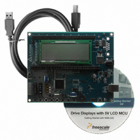
DEMO BOARD FOR LG32 FAMILY MCU
Manufacturer
Freescale Semiconductor
Type
MCUr
Datasheets
1.DEMO9S08LG32.pdf
(50 pages)
2.DEMO9S08LG32.pdf
(25 pages)
3.DEMO9S08LG32.pdf
(10 pages)
4.DEMO9S08LG32.pdf
(2 pages)
5.CWS-H08-STDED-CX.pdf
(4 pages)
Specifications of DEMO9S08LG32
Contents
Board, CD
Processor To Be Evaluated
MC9S08LG32x
Data Bus Width
8 bit
Interface Type
USB
Maximum Operating Temperature
+ 85 C
Minimum Operating Temperature
- 40 C
Silicon Manufacturer
Freescale
Core Architecture
HCS08
Core Sub-architecture
HCS08
Silicon Core Number
MC9S08
Silicon Family Name
S08LG
Rohs Compliant
Yes
For Use With/related Products
MC9S08LG32
Lead Free Status / RoHS Status
Contains lead / RoHS non-compliant


D E M O 9 S 0 8 L G 3 2
U S E R
DEVELOPMENT SUPPORT
Application development and debug for the target MC9S08LG32 is supported through the
background debug mode (BDM) interface. The BDM interface consists of an integrated USB-
Multilink BDM and a 6-pin interface header (BDM_PORT). The BDM_PORT header allows
connecting a HCS12/HCS08 BDM cable.
Integrated BDM
The DEMO9S08LG32 board features an integrated USB-Multilink BDM from P&E
Microcomputer Systems. The integrated USB-Multilink BDM supports application development
and debugging via background debug mode.
integrated USB-Multilink BDM. A USB, type B, connector provides connection from the target
board to the host PC.
The integrated USB-Multilink BDM provides power and ground to the target board eliminating
the need to power the board externally. Power from the USB-Multilink BDM is derived from the
USB bus; therefore, total current consumption for the target board, and connected circuitry,
must not exceed 500mA. This current limit describes the current supplied by the USB cable
to the BDM circuit, the target board, and any connected circuitry. Excessive current drain will
violate the USB specification causing the bus to disconnect. Damage to the host PC USB hub
or the target board may result.
USB-BDM OPTION Headers
Option header JP2 connects two timer channels to the USB-BDM to facilitate the Signal
Analyzer functionality. Installing an option jumper shunt enables the selected timer channel to
the BDM circuitry.
Figure 2: JP1 Option Header
BDM_PORT Header
A compatible HCS12 BDM cable may also attach to the 6-pin BDM interface header
(BDM_PORT). Figure 3 below shows the pin-out for the BDM_PORT header.
G U I D E
DATA1
DATA2
• •
• •
TPM2CH4 input to Signal Analyzer
TPM2CH3 input to Signal Analyzer
8
All necessary signals are provided by the
F E B R U A R Y
2 4 ,
2 0 0 9
Related parts for DEMO9S08LG32
Image
Part Number
Description
Manufacturer
Datasheet
Request
R

Part Number:
Description:
Manufacturer:
Freescale Semiconductor, Inc
Datasheet:
Part Number:
Description:
Manufacturer:
Freescale Semiconductor, Inc
Datasheet:
Part Number:
Description:
Manufacturer:
Freescale Semiconductor, Inc
Datasheet:
Part Number:
Description:
Manufacturer:
Freescale Semiconductor, Inc
Datasheet:
Part Number:
Description:
Manufacturer:
Freescale Semiconductor, Inc
Datasheet:
Part Number:
Description:
Manufacturer:
Freescale Semiconductor, Inc
Datasheet:
Part Number:
Description:
Manufacturer:
Freescale Semiconductor, Inc
Datasheet:
Part Number:
Description:
Manufacturer:
Freescale Semiconductor, Inc
Datasheet:
Part Number:
Description:
Manufacturer:
Freescale Semiconductor, Inc
Datasheet:
Part Number:
Description:
Manufacturer:
Freescale Semiconductor, Inc
Datasheet:
Part Number:
Description:
Manufacturer:
Freescale Semiconductor, Inc
Datasheet:
Part Number:
Description:
Manufacturer:
Freescale Semiconductor, Inc
Datasheet:
Part Number:
Description:
Manufacturer:
Freescale Semiconductor, Inc
Datasheet:
Part Number:
Description:
Manufacturer:
Freescale Semiconductor, Inc
Datasheet:
Part Number:
Description:
Manufacturer:
Freescale Semiconductor, Inc
Datasheet: