DEMO9S08LG32 Freescale Semiconductor, DEMO9S08LG32 Datasheet
DEMO9S08LG32
Specifications of DEMO9S08LG32


Related parts for DEMO9S08LG32

DEMO9S08LG32 Summary of contents
Page 1
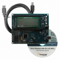
... DEMO9S08LG32 Demonstration Board for Freescale MC9S08LG32 Microcontroller USER GUIDE Web Site: support@axman.com Support: www.axman.com ...
Page 2
CAUTIONARY NOTES ..............................................................................................................5 TERMINOLOGY.........................................................................................................................5 FEATURES ................................................................................................................................6 REFERENCES ...........................................................................................................................7 MEMORY MAP ..........................................................................................................................7 SOFTWARE DEVELOPMENT...................................................................................................7 DEVELOPMENT SUPPORT ......................................................................................................8 INTEGRATED BDM .............................................................................................................. 8 USB-BDM OPTION HEADERS ......................................................................................... 8 BDM_PORT HEADER........................................................................................................... 8 POWER ......................................................................................................................................9 POWER ...
Page 3
...
Page 4
... Figure 15: LCD Enable Option Header – JP1...........................................................................19 Date November 21, 2008 December 02, 2008 February 24, 2009 FIGURES REVISION Rev A Initial Release Updated DEMO9S08LG32 connector pins, features, MCU I/O port, B and demonstration board diagram. Minor updates to format and corrections to content. Added Notes and C Caution boxes 4 Comments ...
Page 5
... EMC Information on the DEMO9S08LG32 board: a) This product as shipped from the factory with associated power supplies and cables, has been verified to meet with requirements of CE and the FCC as a CLASS A product. ...
Page 6
... FEATURES The DEMO9S08LG32 is a demonstration board for the MC9S08LG32 microcontroller. Application development is quick and easy with the integrated USB-BDM, sample software tools, and examples. An optional BDM_PORT port is also provided to allow use of a BDM_PORT cable. One, 80-pin connector provides access to all IO signals on the target MCU. • ...
Page 7
... PC operating a debug interface. CodeWarrior Development Studio for Microcontrollers is supplied with this board for application development and debug. Refer to the supporting CodeWarrior documentation for details on use and capabilities. DEMO9S08LG32 User Guide (this document) DEMO9S08LG32 Schematic Rev. A DEMO9S08LG32 Top Silk, Rev A ...
Page 8
... Multilink BDM and a 6-pin interface header (BDM_PORT). The BDM_PORT header allows connecting a HCS12/HCS08 BDM cable. Integrated BDM The DEMO9S08LG32 board features an integrated USB-Multilink BDM from P&E Microcomputer Systems. The integrated USB-Multilink BDM supports application development and debugging via background debug mode. ...
Page 9
... RESET VDD POWER The DEMO9S08LG32 uses several methods to apply power to the board. An option header allows selection between the various power inputs. For application development and debug, the board may be powered from the USB BDM. The 2.0mm, center-positive, barrel connector (VIN) supports stand-alone operation and higher power requirements. Power may also be applied to connector J1 or the board may be configured to supply power from connector J1 to external circuitry ...
Page 10
Total power from the USB-BDM is limited to 500 mA. Exceeding this limit violates the USB specification and will ...
Page 11
... Consult the MC9S08LG32 reference manual for details LVD operation. TIMING The DEMO9S08LG32 internal timing source is active from RESET by default. An external 32 kHz XTAL oscillator, configured for low-power operation, is also provided. Refer to the MC9S08LG32 Reference Manual for details on configuring the selected timing source. ...
Page 12
RS-232 An RS-232 translator provides RS-232 to TTL/CMOS logic level translation on the COM connector. The COM connector is a 9-pin Dsub, right-angle connector. A ferrite bead on shield ground provides ...
Page 13
... RXD position enables COM through the DB9 connector while the TXD position enables COM through the integrated USB-BDM. LCD The DEMO9S08LG32 provides custom LCD glass connected directly to the target MCU. Refer to the MC9S08LG32 Reference Manual for details on use and configuration. A row of option jumpers located below the LCD module allows each LCD signal to be disconnected from the associated LCD input ...
Page 14
... I/O. The User1, User2, and Buz option header blocks enable or disable each User I/O function individually. Buzzer The DEMO9S08LG32 target board provides an externally modulated piezo-buzzer for audible applications. A push-pull drive circuit allows the target MCU to easily drive the buzzer at a center frequency of 2300 Hz. Figure 10 below shows the USER enable position and associated signal for the buzzer ...
Page 15
... PTH1 will cause a target board POR. User LED’s The DEMO9S08LG32 target board provides 8, green, LEDs for output indication. Each LED is configured for active-low operation. A series, current-limit resistor prevents excessive diode current. Figure 12 below shows the USER1 enable position and associated signal for each LED ...
Page 16
... PTH1 will cause a target board POR. Pushbutton Switches The DEMO9S08LG32 provides 8 push-button switches for user input. switch is configured for active-low operation. No bias is applied to these push-button inputs. Use of target MCU internal pull-ups is required for proper operation. Figure 13 below shows the USER2 enable position and associated signal for each user switch ...
Page 17
MCU I/O PORT The MCU I/O PORT connector provides access to the MC9S08LG32 I/O signals. Figure 14 below show the pin-out for the MCU I/O connector. Figure 14: MCU I/O PORT ...
Page 18
LCD ENABLE OPTION HEADER The LCD Enable Option Header allows the user to disable any LCD signal to the ...
Page 19
Figure 15: LCD Enable Option Header – JP1 MCU MCU Signal Pin # 14 PTB0/LCD29 13 PTB1/LCD30 12 PTB4/LCD37 ...
Page 20
SCHEMATIC APPENDIX ...
Page 21
...
Page 22
Bill of Material Item Qty Title Detail 1 1 Buzzer-Thru Mag,2.3Khz, Cap-Cer-Smt(R) (0603) .01uF,50V 3 21 Cap-Cer-Smt(R) (0603) .1uF,16V 4 1 ...
Page 23
Conn-USB-Thru(R) USB-B, Crystal-Cylndr-Thru(R) (3X8) 32.768KHz,3. Crystal-Smt(R) (HC49S) 12.0MHz,18PF 14 1 Dio-Zener-Smt (Sot23) MMBZ5232B ...
Page 24
LED-Smt(R) (1206) Green 12 3 LED-Smt(R) (1206) Red 69 1 Misc-Not Installed 70 1 Part-Not Installed 68 ...
Page 25
Res-Carb-Smt(R) (0603) 510 Ohm, Res-Carb-Smt(R) (0603) 680 Ohm, Res-MF-Smt(R) (0805) 33 Ohm,1% 51 ...