DEMOQE128 Freescale Semiconductor, DEMOQE128 Datasheet - Page 39
DEMOQE128
Manufacturer Part Number
DEMOQE128
Description
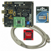
DEMO BOARD FOR QE128 FLEXIS
Manufacturer
Freescale Semiconductor
Series
Flexis™r
Type
MCUr
Specifications of DEMOQE128
Contents
Demo Board, USB Cable, Documentation and Design Files
Processor To Be Evaluated
MC9S08QE128 and MCF51QE128
Data Bus Width
8 bit, 32 bit
Interface Type
RS-232, USB
Silicon Manufacturer
Freescale
Core Architecture
Coldfire, HCS08
Core Sub-architecture
Coldfire V1, HCS08
Silicon Core Number
MCF51Q, MC9S08
Rohs Compliant
Yes
Tool Type
Demonstration Board
Cpu Core
HCS08
For Use With/related Products
MC9S08QE128, MCF51QE128
For Use With
DEMOACEX - BOARD EXPANSION FOR DEMO KIT
Lead Free Status / RoHS Status
Lead free / RoHS Compliant
Available stocks
Company
Part Number
Manufacturer
Quantity
Price
Company:

Part Number:
DEMOQE128
Manufacturer:
Freescale Semiconductor
Quantity:
135
Company:
Part Number:
DEMOQE128
Manufacturer:
NINEX
Quantity:
3 500


7.2
8
8.1
8.1.1
DEMOQE128 User Manual
JUMPER SETTINGS
Serial Accelerometer Application
System Power
J3 - Regulator Input Selection Jumper
This microcontroller application samples the state of the on-board three-axis
accelerometer using on-chip A/D converter channels. This data is converted
into ASCII characters and sent out using the serial pins of the QE128
processor. These serial pins may be connected to either serial port hardware
or to P&E’s virtual serial port (which is part of the Embedded Multilink design).
This connection is controlled by jumpers J6 and J7.
P&E has two PC-based DEMOQE Toolkit applications which allow the serial
port data generated by this application to be graphed. These are documented
in Section 6.4 - DEMOQE Accelerometer Demo Application and Section
6.5 - DEMOQE Serial Grapher Application.
Usage of this application is documented in the Section 3.4 - LAB 3: Measure
Performance between 8-Bit and 32-Bit.
The QE128 processor may obtain its power from either the on-board
regulator, a 2-cell battery pack, or through MCU_PORT J1. The on-board
regulator obtains its input from either the Embedded Multilink circuitry or a
2.5mm barrel connector. The on-board regulator can regulate the output to
either 2.1V or 3V. The DEMOQE128 is fully functional at both voltages. Power
input and voltage selection are achieved by using 3 option headers.
Jumper 3 determines whether the DEMOQE128’s on-board regulator obtains
its power from the DC power jack or from the Embedded Multilink circuitry.
The regulator input selection is mutually exclusive. It prevents power input
contention from damaging the board and the host. Figure 8-1 shows the
regulator input selection details.
Select regulator input from DC power jack. A 5-8VDC center positive
35
Related parts for DEMOQE128
Image
Part Number
Description
Manufacturer
Datasheet
Request
R

Part Number:
Description:
DEM FOR STM8L15X LOW PWR MODES
Manufacturer:
STMicroelectronics
Datasheet:

Part Number:
Description:
Manufacturer:
Freescale Semiconductor, Inc
Datasheet:
Part Number:
Description:
Manufacturer:
Freescale Semiconductor, Inc
Datasheet:
Part Number:
Description:
Manufacturer:
Freescale Semiconductor, Inc
Datasheet:
Part Number:
Description:
Manufacturer:
Freescale Semiconductor, Inc
Datasheet:
Part Number:
Description:
Manufacturer:
Freescale Semiconductor, Inc
Datasheet:
Part Number:
Description:
Manufacturer:
Freescale Semiconductor, Inc
Datasheet:
Part Number:
Description:
Manufacturer:
Freescale Semiconductor, Inc
Datasheet:
Part Number:
Description:
Manufacturer:
Freescale Semiconductor, Inc
Datasheet:
Part Number:
Description:
Manufacturer:
Freescale Semiconductor, Inc
Datasheet:
Part Number:
Description:
Manufacturer:
Freescale Semiconductor, Inc
Datasheet:
Part Number:
Description:
Manufacturer:
Freescale Semiconductor, Inc
Datasheet:
Part Number:
Description:
Manufacturer:
Freescale Semiconductor, Inc
Datasheet:
Part Number:
Description:
Manufacturer:
Freescale Semiconductor, Inc
Datasheet:
Part Number:
Description:
Manufacturer:
Freescale Semiconductor, Inc
Datasheet: