DEMOQE128 Freescale Semiconductor, DEMOQE128 Datasheet - Page 17
DEMOQE128
Manufacturer Part Number
DEMOQE128
Description
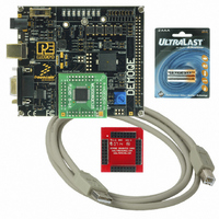
DEMO BOARD FOR QE128 FLEXIS
Manufacturer
Freescale Semiconductor
Series
Flexis™r
Type
MCUr
Specifications of DEMOQE128
Contents
Demo Board, USB Cable, Documentation and Design Files
Processor To Be Evaluated
MC9S08QE128 and MCF51QE128
Data Bus Width
8 bit, 32 bit
Interface Type
RS-232, USB
Silicon Manufacturer
Freescale
Core Architecture
Coldfire, HCS08
Core Sub-architecture
Coldfire V1, HCS08
Silicon Core Number
MCF51Q, MC9S08
Rohs Compliant
Yes
Tool Type
Demonstration Board
Cpu Core
HCS08
For Use With/related Products
MC9S08QE128, MCF51QE128
For Use With
DEMOACEX - BOARD EXPANSION FOR DEMO KIT
Lead Free Status / RoHS Status
Lead free / RoHS Compliant
Available stocks
Company
Part Number
Manufacturer
Quantity
Price
Company:

Part Number:
DEMOQE128
Manufacturer:
Freescale Semiconductor
Quantity:
135
Company:
Part Number:
DEMOQE128
Manufacturer:
NINEX
Quantity:
3 500


DEMOQE128 User Manual
7. Click “Finish.” In the background CodeWarrior will transform your
8. If the Logic Analyzer utility is open, click the “Close Port” button on
9. Turn the board power switch to OFF.
10.
11.
12.
13.
14.
15.
16.
project to the 32-bit microcontroller with no software changes needed.
An informational “Project Messages” window may appear letting you
know that changes have been made to the project.
that utility.
Switch the green 8-bit S08 daughter card with the red 32-bit Cold-
Fire V1 daughter card. Make sure to align pin 1 (as marked by
arrows) on the daughter card with pin 1 on the board.
Turn the board power switch to ON.
Compile the transformed Quick Start Application and start the pro-
cess of programming it into the flash on the 32-bit QE128 microcon-
troller by clicking on the debugger launch button shown here :
From the Connection Manager menu, select “USB1: DEMOQE”
port and click on “Connect (Reset).”
From the Loader Warning menu, click on “OK” to allow the debug-
ger to mass erase the microcontroller’s on-chip flash memory and
program it with the new application.
Click on the GO button in the debugger to run the application. The
GO button is shown here:
Repeat Step 4 of the Quick Start Guide instructions to observe the
32-bit QE128 device running the same application as the 8-bit
QE128 device did previously.
Figure 3-7: IDE Debugger Launch Button
Figure 3-8: Debugger GO Button
Figure 3-6: MCU Change Wizard
13
Related parts for DEMOQE128
Image
Part Number
Description
Manufacturer
Datasheet
Request
R

Part Number:
Description:
DEM FOR STM8L15X LOW PWR MODES
Manufacturer:
STMicroelectronics
Datasheet:

Part Number:
Description:
Manufacturer:
Freescale Semiconductor, Inc
Datasheet:
Part Number:
Description:
Manufacturer:
Freescale Semiconductor, Inc
Datasheet:
Part Number:
Description:
Manufacturer:
Freescale Semiconductor, Inc
Datasheet:
Part Number:
Description:
Manufacturer:
Freescale Semiconductor, Inc
Datasheet:
Part Number:
Description:
Manufacturer:
Freescale Semiconductor, Inc
Datasheet:
Part Number:
Description:
Manufacturer:
Freescale Semiconductor, Inc
Datasheet:
Part Number:
Description:
Manufacturer:
Freescale Semiconductor, Inc
Datasheet:
Part Number:
Description:
Manufacturer:
Freescale Semiconductor, Inc
Datasheet:
Part Number:
Description:
Manufacturer:
Freescale Semiconductor, Inc
Datasheet:
Part Number:
Description:
Manufacturer:
Freescale Semiconductor, Inc
Datasheet:
Part Number:
Description:
Manufacturer:
Freescale Semiconductor, Inc
Datasheet:
Part Number:
Description:
Manufacturer:
Freescale Semiconductor, Inc
Datasheet:
Part Number:
Description:
Manufacturer:
Freescale Semiconductor, Inc
Datasheet:
Part Number:
Description:
Manufacturer:
Freescale Semiconductor, Inc
Datasheet: