DEMO9S08JS16 Freescale Semiconductor, DEMO9S08JS16 Datasheet
DEMO9S08JS16
Specifications of DEMO9S08JS16


Related parts for DEMO9S08JS16

DEMO9S08JS16 Summary of contents
Page 1
... USB Microcontrollers DEMO9S08JS16 Lab tutorial DEMO9S08JS16—Lab Tutorial ...
Page 2
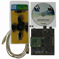
... These labs provide various USB examples included with the complimentary USB stack for MC9S08JS16 (JS16) microcontroller (MCU). Instructions to install the software stack are explained in the DEMO9S08JS16 Quick Start Guide (DEMO9S08JS16 QSG). Start each lab with the board powered “On” and both provided USB cables connected between host and board ...
Page 3
... Click button labeled “PTG3” for Caps Lock key action; the LED labeled “PTE3” will be switched on or off. 13. Click the Num Lock and/or Caps Lock key on your computer keyboard; the “PTE2” and/or “PTE3” LEDs will turn on/off respectively. DEMO9S08JS16—Lab Tutorial ...
Page 4
... DEMO9S08JS16—Lab Tutorial LAB 2 CDC Serial Bridge This lab demonstrates a bridge between CDC and a serial port (SCI). The CDC-Serial example emulates a virtual serial port on the PC. The instructions below will guide you to program the JS16 MCU, install the driver for the virtual serial port and communicate with a true serial port using the two independent terminal windows ...
Page 5
... This lab will demonstrate how to use the USB bootloader to update/download the firmware. The GUI for the USB bootloader needs to be installed before the beginning of this lab. The installation is described in the DEMO9S08JS16 Quick Start Guide. A detailed document on the USB bootloader is available for reference, “Bootloader GUI User Manual.” The following steps demonstrate how to update/download the firmware to the JS16 flash ...
Page 6
... DEMO9S08JS16—Lab Tutorial DEMO9S08JS16 LEDs External Power Connector P&E Micro Embedded Multi-Link USB Connector Mini-AB USB Conector Figure 1. DEMO9S08JS16 Push Buttons Speaker DC9S08JS16 Daughter Card ...
Page 7
... MCU Port Connector Pin Out The following is a pinout diagram for the MCU port connector on the DEMO9S08JS16 board Rev D. Symbol VDD VSS PTA7/KBIP7/TxD PTA6/KBIP6/RxD PTB3/BLMS PTA1/KBIP1/MISO PTA0/KBIP0/TPMCH0 PTA5/KBIP5/TPMCH1 PTA2/KBIP2/MOSI PTA1/KBIP1/MISO PTA3/KBIP3/SPSCK PTA4/KBIP4/SS N/C N/C N/C N/C N/C N/C N/C N/C Number ...
Page 8
... DEMO9S08JS16—Lab Tutorial Default Jumper Settings The following is a list of default jumper settings for the DEMOJM board used for the MC9S08JS16 demo. The settings listed indicate the ON (or installed) position. Jumper Installed Settings J3 3&4 J4 ALL OFF J6 2&3 J7 1&2 J8 1&2, 3&4 J10 ...