DEMO9S08QE8 Freescale Semiconductor, DEMO9S08QE8 Datasheet - Page 10
DEMO9S08QE8
Manufacturer Part Number
DEMO9S08QE8
Description
BOARD DEMO FOR MC9S08Q
Manufacturer
Freescale Semiconductor
Series
Flexis™r
Type
MCUr
Datasheets
1.DEMO9S08QE8.pdf
(6 pages)
2.DEMO9S08QE8.pdf
(41 pages)
3.DEMO9S08QE8.pdf
(3 pages)
4.DEMO9S08QE8.pdf
(2 pages)
Specifications of DEMO9S08QE8
Contents
Demo Board
Silicon Manufacturer
Freescale
Core Architecture
HCS08
Core Sub-architecture
HCS08
Silicon Core Number
MC9S08
Silicon Family Name
Flexis - S08QE
Rohs Compliant
Yes
For Use With/related Products
MC9S08QE8
For Use With
DEMOACEX - BOARD EXPANSION FOR DEMO KIT
Lead Free Status / RoHS Status
Lead free / RoHS Compliant


3.3.2
3.4
6
Quick Startup
Installing P&E Resources
into your computer’s CD-ROM drive. A start-up window will automatically
appear. Select CodeWarrior Installation and follow the on-screen instructions.
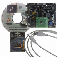
Use the DEMOQE Resources CD-ROM to access and install P&E resources
for the DEMO9S08QE8. These materials are not required for operation. The
support materials contained on the DEMOQE Resources CD-ROM are listed
in Section 1.4 - Recommended Materials On DEMOQE Resources CD.
Only a few steps are required to get the DEMO9S08QE8 up and running:
Step 1.
Step 2.
Step 3.
Step 4.
Step 5.
Step 6.
If you do not have CodeWarrior Development Studio version 6.0
installed on your computer, please install it using the
accompanying CD-ROM. Additional information regarding
CodeWarrior can be found at www.freescale.com.
Remove the DEMO9S08QE8 demonstration board from its anti-
static pouch. The green MC9S08QE8 daughter card should be
plugged into the header on the base board.
Connect the USB cable from your computer to the
DEMO9S08QE8 demonstration board. Depending on your
operating system, you may need to follow steps to install the USB
driver from the DEMOQE Resources CD-ROM. Once the USB
cable is connected properly the green USB LED on the
DEMO9S08QE8 should illuminate.
Turn on the DEMO9S08QE8 power switch (K6). The red Power
LED should illuminate.
Press the buttons labelled PTA2 and PTA3. When each button is
pressed a different tone will be emitted, and the light intensity of
the PTC0 LED will change. The LEDs labelled PTC1 and PTC2
(for PTA2) or PTC3 and PTC4 (for PTA3) should illuminate. In
addition, the light intensity of the LED labeled PTC1 should vary as
the potentiometer is rotated.
Optionally, you may run the DEMOQE Logic Analyzer Application
available in the DEMOQE toolkit on the CD. This PC-based
application graphs the IN0 and IN1 signals on the DEMOQE
board. If both J11 jumpers are installed, IN0 shows PTC0 and IN1
DEMO9S08QE8 User Manual
Related parts for DEMO9S08QE8
Image
Part Number
Description
Manufacturer
Datasheet
Request
R

Part Number:
Description:
Manufacturer:
STMicroelectronics
Datasheet:

Part Number:
Description:
DEMO BOARD FOR HMC6042/HMC1041Z
Manufacturer:
Honeywell Microelectronics & Precision Sensors

Part Number:
Description:
DEMO BOARD FOR HMC1042L/HMC1041Z
Manufacturer:
Honeywell Microelectronics & Precision Sensors
Datasheet:

Part Number:
Description:
KIT DEMO 4 SENSOR CHAN RS232
Manufacturer:
VTI Technologies
Datasheet:


Part Number:
Description:
DEMO: DC Power Supply, 32 Volts, 3 Amps
Manufacturer:
Tektronix
Part Number:
Description:
DEMO: Programmable DC Power Supply, 32 Volts, 3 Amps
Manufacturer:
Tektronix

Part Number:
Description:
Manufacturer:
Freescale Semiconductor, Inc
Datasheet:
Part Number:
Description:
Manufacturer:
Freescale Semiconductor, Inc
Datasheet:
Part Number:
Description:
Manufacturer:
Freescale Semiconductor, Inc
Datasheet:
Part Number:
Description:
Manufacturer:
Freescale Semiconductor, Inc
Datasheet:
Part Number:
Description:
Manufacturer:
Freescale Semiconductor, Inc
Datasheet:
Part Number:
Description:
Manufacturer:
Freescale Semiconductor, Inc
Datasheet:
Part Number:
Description:
Manufacturer:
Freescale Semiconductor, Inc
Datasheet:
Part Number:
Description:
Manufacturer:
Freescale Semiconductor, Inc
Datasheet: