C8051F226DK Silicon Laboratories Inc, C8051F226DK Datasheet - Page 16
C8051F226DK
Manufacturer Part Number
C8051F226DK
Description
DEV KIT F220/221/226/230/231/236
Manufacturer
Silicon Laboratories Inc
Type
MCUr
Datasheet
1.C8051F226DK.pdf
(146 pages)
Specifications of C8051F226DK
Contents
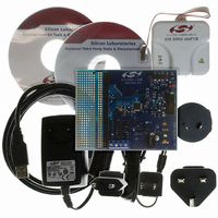
Evaluation Board, Power Supply, USB Cables, Adapter and Documentation
Processor To Be Evaluated
C8051F22x and C8051F23x
Interface Type
USB
Silicon Manufacturer
Silicon Labs
Core Architecture
8051
Silicon Core Number
C8051F226
Silicon Family Name
C8051F2xx
Lead Free Status / RoHS Status
Contains lead / RoHS non-compliant
For Use With/related Products
C8051F220, 221, 226, 230, 231, 236
Lead Free Status / Rohs Status
Lead free / RoHS Compliant
Other names
336-1241


C8051F2xx
With the CIP-51's maximum system clock at 25 MHz, it has a peak throughput of 25 MIPS. Figure 1.5
shows a comparison of peak throughputs of various 8-bit microcontroller cores with their maximum system
clocks.
1.1.3. Additional Features
The C8051F206, C8051F220/1/6 and C8051F230/1/6 have several key enhancements both inside and
outside the CIP-51 core to improve overall performance and ease of use in end applications.
The extended interrupt handler provides 22 interrupt sources into the CIP-51 (as opposed to 7 for the stan-
dard 8051), allowing the numerous analog and digital peripherals to interrupt the controller. (An interrupt
driven system requires less intervention by the MCU, giving it more effective throughput.) The extra inter-
rupt sources are very useful when building multi-tasking, real-time systems.
There are up to six reset sources for the MCU: an on-board
clock detector, a voltage level detection from Comparator 0, a forced software reset, and an external reset
pin. The RST pin is bi-directional, accommodating an external reset, or allowing the internally generated
reset to be output on the RST pin. The on-board
(digital 1). The user may disable each reset source except for the
software. The watchdog timer may be permanently enabled in software after a power-on reset during
MCU initialization.
The MCU has an internal, stand-alone clock generator that is used by default as the system clock after
reset. If desired, the clock source may be switched "on the fly" to the external oscillator, which can use a
crystal, ceramic resonator, capacitor, RC, or external clock source to generate the system clock. This can
be extremely useful in low power applications, allowing the MCU to run from a slow (power saving) exter-
nal crystal source, while periodically switching to the fast (up to 16MHz) internal oscillator as needed.
16
Figure 1.5. Comparison of Peak MCU Throughputs
25
20
15
10
5
(25 MHz clk)
Silicon Labs
CIP-51
(33 MHz clk)
PIC17C75x
Rev. 1.6
Microchip
V
DD monitor is enabled by pulling the MONEN pin high
V
(33 MHz clk)
DD monitor, a Watchdog Timer, a missing
Philips
80C51
V
DD monitor and Reset Input Pin from
(16 MHz clk)
ADuC812
8051
Related parts for C8051F226DK
Image
Part Number
Description
Manufacturer
Datasheet
Request
R

Part Number:
Description:
SMD/C°/SINGLE-ENDED OUTPUT SILICON OSCILLATOR
Manufacturer:
Silicon Laboratories Inc
Part Number:
Description:
Manufacturer:
Silicon Laboratories Inc
Datasheet:
Part Number:
Description:
N/A N/A/SI4010 AES KEYFOB DEMO WITH LCD RX
Manufacturer:
Silicon Laboratories Inc
Datasheet:
Part Number:
Description:
N/A N/A/SI4010 SIMPLIFIED KEY FOB DEMO WITH LED RX
Manufacturer:
Silicon Laboratories Inc
Datasheet:
Part Number:
Description:
N/A/-40 TO 85 OC/EZLINK MODULE; F930/4432 HIGH BAND (REV E/B1)
Manufacturer:
Silicon Laboratories Inc
Part Number:
Description:
EZLink Module; F930/4432 Low Band (rev e/B1)
Manufacturer:
Silicon Laboratories Inc
Part Number:
Description:
I°/4460 10 DBM RADIO TEST CARD 434 MHZ
Manufacturer:
Silicon Laboratories Inc
Part Number:
Description:
I°/4461 14 DBM RADIO TEST CARD 868 MHZ
Manufacturer:
Silicon Laboratories Inc
Part Number:
Description:
I°/4463 20 DBM RFSWITCH RADIO TEST CARD 460 MHZ
Manufacturer:
Silicon Laboratories Inc
Part Number:
Description:
I°/4463 20 DBM RADIO TEST CARD 868 MHZ
Manufacturer:
Silicon Laboratories Inc
Part Number:
Description:
I°/4463 27 DBM RADIO TEST CARD 868 MHZ
Manufacturer:
Silicon Laboratories Inc
Part Number:
Description:
I°/4463 SKYWORKS 30 DBM RADIO TEST CARD 915 MHZ
Manufacturer:
Silicon Laboratories Inc
Part Number:
Description:
N/A N/A/-40 TO 85 OC/4463 RFMD 30 DBM RADIO TEST CARD 915 MHZ
Manufacturer:
Silicon Laboratories Inc
Part Number:
Description:
I°/4463 20 DBM RADIO TEST CARD 169 MHZ
Manufacturer:
Silicon Laboratories Inc