STM32CMICOS-EVAL STMicroelectronics, STM32CMICOS-EVAL Datasheet - Page 7
STM32CMICOS-EVAL
Manufacturer Part Number
STM32CMICOS-EVAL
Description
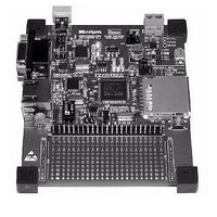
EVAL BOARD
Manufacturer
STMicroelectronics
Type
MCUr
Specifications of STM32CMICOS-EVAL
Contents
Board
Tool Type
Development Software Support
Core Architecture
ARM
Operating Supply Voltage
3.3 V
For Use With/related Products
STM32F107
Lead Free Status / RoHS Status
Lead free / RoHS Compliant
Other names
497-10064


STM32-MICRIUM
2.3
2.4
2.5
2.6
2.7
Reset sources
The reset signal of the STM32-MICRIUM evaluation board is active low.
The reset source may come from:
CAN (controller area network)
The STM32-MICRIUM evaluation board supports one channel of CAN2.0A/B-compliant
CAN bus communication based on a 3.3V CAN transceiver.
The CAN transceiver (U1) is configured for high-speed mode.
The CAN bus is available on extension connector CN3 pin 28 (CAN_L) and pin 30 (CAN_H).
The CAN interface is connected to CAN1 remapped (PD0, PD1) of the STM32F107VCT.
The CAN terminal (120 ohm), available on the board, can be connected on the bus by the
jumper JP1.
Table 3.
RS-232C
The RS-232 communication with hardware flow control is supported by CN7 (a 9-pin D-type
RS-232 connector) and the transceiver U8, which is connected to USART2 remapped on
PD3 to PD6 of STM32F107VCT on STM32-MICRIUM evaluation board.
SD/MMC card
An SD/MMC card (Secure Digital/Multi-Media Card) connector (CN6) is available on the
board, but the card is not provided by default with the product. The SD/MMC card is
connected to SPI1 of STM32F107VCT (PA5 to PA7 without remap) with chip select on PA8
and card detection on PE6.
USB-OTG (USB ON-THE-GO)
The STM32-MICRIUM evaluation board supports USB-OTG full-speed communication via a
USB Micro-AB connector (CN8) and USB power switch (U9) connected to VBUS. The
evaluation board cannot be powered by this USB connector.
The green LED LD6 turns on when the power switch (U9) is ON, which corresponds to USB-
host mode. In this case, the 5V VBUS is provided by the board to a USB device connected
on CN8. The red LED LD7 turns on when an over-current condition is detected.
JP1
Jumper
Reset button B1 in bottom right of the board.
Embedded J-Link.
Extension connector CN3 pin 45 (pin header).
CAN terminal resistor is enabled when JP1 is fitted. Default setting: Not fitted.
STM32-MICRIUM evaluation board CAN related jumper
Doc ID 16173 Rev 2
Description
Configuration
7/27
Related parts for STM32CMICOS-EVAL
Image
Part Number
Description
Manufacturer
Datasheet
Request
R

Part Number:
Description:
STMicroelectronics [RIPPLE-CARRY BINARY COUNTER/DIVIDERS]
Manufacturer:
STMicroelectronics
Datasheet:
Part Number:
Description:
STMicroelectronics [LIQUID-CRYSTAL DISPLAY DRIVERS]
Manufacturer:
STMicroelectronics
Datasheet:

Part Number:
Description:
BOARD EVAL FOR MEMS SENSORS
Manufacturer:
STMicroelectronics
Datasheet:
Part Number:
Description:
NPN TRANSISTOR POWER MODULE
Manufacturer:
STMicroelectronics
Datasheet:
Part Number:
Description:
TURBOSWITCH ULTRA-FAST HIGH VOLTAGE DIODE
Manufacturer:
STMicroelectronics
Datasheet:
Part Number:
Description:
Manufacturer:
STMicroelectronics
Datasheet:
Part Number:
Description:
DIODE / SCR MODULE
Manufacturer:
STMicroelectronics
Datasheet:
Part Number:
Description:
DIODE / SCR MODULE
Manufacturer:
STMicroelectronics
Datasheet:
Part Number:
Description:
Search -----> STE16N100
Manufacturer:
STMicroelectronics
Datasheet:
Part Number:
Description:
Search ---> STE53NA50
Manufacturer:
STMicroelectronics
Datasheet:
Part Number:
Description:
NPN Transistor Power Module
Manufacturer:
STMicroelectronics
Datasheet:
Part Number:
Description:
DIODE / SCR MODULE
Manufacturer:
STMicroelectronics
Datasheet: