STM8L1526-EVAL STMicroelectronics, STM8L1526-EVAL Datasheet - Page 20
STM8L1526-EVAL
Manufacturer Part Number
STM8L1526-EVAL
Description
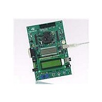
BOARD EVAL FOR STM8L152C6
Manufacturer
STMicroelectronics
Series
STM8L EnergyLiter
Type
MCUr
Specifications of STM8L1526-EVAL
Contents
Board
Processor To Be Evaluated
STM8L15x
Data Bus Width
8 bit
Interface Type
RS-232, USB, SPI, USART
Operating Supply Voltage
5 V
Core Architecture
STM8
Core Sub-architecture
STM8
Silicon Core Number
STM8
Silicon Family Name
STM8L1xx
Silicon Manufacturer
ST Micro
For Use With/related Products
STM8L152C6
Lead Free Status / RoHS Status
Lead free / RoHS Compliant
Other names
497-10590
Available stocks
Company
Part Number
Manufacturer
Quantity
Price
Company:

Part Number:
STM8L1526-EVAL
Manufacturer:
OMRON
Quantity:
30 000


Hardware layout and configuration
2.17
Note:
20/46
The measurement is performed in three steps:
1.
2.
3.
IR LED
One IR LED, LD6, is driven by either PA0 through two transistors T1 and T8, or PA0 directly;
depending on the setting of the solder bridge SB7.
Table 12.
JP6 needs to be set correspondingly for IR LED, please refer to
SB7
Solder bridge
Internal reference voltage VREFINT is connected to the comparator inverting input and
Cref to noninverting input to measure the time required to charge the capacitor to
internal reference voltage VREFINT by PE0 used as output through Rref.
The potentiometer is connected to inverting input to measure the time required to
charge Cref to the voltage on potentiometer.
The potentiometer voltage is calculated by software interpolation or using a conversion
table.
IR LED related solder bridges
LD6 is driven by PA0 through two transistors, T1 and T8, when SB7 is set as pad1
connected to pad2 (default setting).
LD6 is driven by PA0 directly when SB7 is set as pad2 connected to pad3.
Doc ID 15437 Rev 1
Description
Table 9
for details.
STM8L1526-EVAL
Related parts for STM8L1526-EVAL
Image
Part Number
Description
Manufacturer
Datasheet
Request
R

Part Number:
Description:
STMicroelectronics [RIPPLE-CARRY BINARY COUNTER/DIVIDERS]
Manufacturer:
STMicroelectronics
Datasheet:
Part Number:
Description:
STMicroelectronics [LIQUID-CRYSTAL DISPLAY DRIVERS]
Manufacturer:
STMicroelectronics
Datasheet:

Part Number:
Description:
BOARD EVAL FOR MEMS SENSORS
Manufacturer:
STMicroelectronics
Datasheet:
Part Number:
Description:
NPN TRANSISTOR POWER MODULE
Manufacturer:
STMicroelectronics
Datasheet:
Part Number:
Description:
TURBOSWITCH ULTRA-FAST HIGH VOLTAGE DIODE
Manufacturer:
STMicroelectronics
Datasheet:
Part Number:
Description:
Manufacturer:
STMicroelectronics
Datasheet:
Part Number:
Description:
DIODE / SCR MODULE
Manufacturer:
STMicroelectronics
Datasheet:
Part Number:
Description:
DIODE / SCR MODULE
Manufacturer:
STMicroelectronics
Datasheet:
Part Number:
Description:
Search -----> STE16N100
Manufacturer:
STMicroelectronics
Datasheet:
Part Number:
Description:
Search ---> STE53NA50
Manufacturer:
STMicroelectronics
Datasheet:
Part Number:
Description:
NPN Transistor Power Module
Manufacturer:
STMicroelectronics
Datasheet:
Part Number:
Description:
DIODE / SCR MODULE
Manufacturer:
STMicroelectronics
Datasheet: