STM8L1526-EVAL STMicroelectronics, STM8L1526-EVAL Datasheet - Page 10
STM8L1526-EVAL
Manufacturer Part Number
STM8L1526-EVAL
Description
BOARD EVAL FOR STM8L152C6
Manufacturer
STMicroelectronics
Series
STM8L EnergyLiter
Type
MCUr
Specifications of STM8L1526-EVAL
Contents
Board
Processor To Be Evaluated
STM8L15x
Data Bus Width
8 bit
Interface Type
RS-232, USB, SPI, USART
Operating Supply Voltage
5 V
Core Architecture
STM8
Core Sub-architecture
STM8
Silicon Core Number
STM8
Silicon Family Name
STM8L1xx
Silicon Manufacturer
ST Micro
For Use With/related Products
STM8L152C6
Lead Free Status / RoHS Status
Lead free / RoHS Compliant
Other names
497-10590
Available stocks
Company
Part Number
Manufacturer
Quantity
Price
Company:

Part Number:
STM8L1526-EVAL
Manufacturer:
OMRON
Quantity:
30 000


Hardware layout and configuration
2.3
2.4
10/46
Reset source
The reset signal of the STM8L1526-EVAL is low active and the reset sources include:
Table 4.
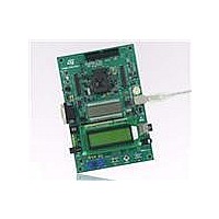
LCD glass module
An LCD glass module (MB821) with 8-digit liquid crystal display is mounted on the
STM8L1526-EVAL evaluation board. It can be connected to the LCD driver of the
STM8L152C6 MCU or can work as a set of jumpers by mounting it in two possible positions,
position IO or position LCD.
JP15
JP13
Jumper
Reset button B1
Debugging tools from SWIM connector CN12 and CN16
Daughterboard from CN10
Embedded ST-LINK
RS-232 connector CN1 for ISP
Position IO. All peripherals (USART, IrDA, MicroSD Card, dot matrix LCD, serial Flash,
LEDs, joystick, bicolor LED, potentiometer, MCU consumption measurement, motor
control and microphone) shared with LCD glass are connected to the STM8L152C6
and the LCD glass is disconnected when LCD glass module is mounted on position IO
as shown below (default setting). See
Position LCD. LCD glass is connected to the LCD driver of the STM8L152C6 and all
peripherals shared with the LCD glass are disconnected when the LCD glass module is
mounted on position LCD as shown below. In this position, as well as the LCD, there
are other resources available on the board:
–
–
–
See
The board Reset is managed by pin 1 of connector CN1 (RS-232 DCD signal)
when JP15 is closed. This configuration is used for boot loader application only.
Default Setting: Not fitted
PA1 is connected to the Reset source listed above when JP13 is set as shown to
the right: (Default setting).
PA1 is connected to ground when JP13 is set as shown to the right. So, the MCU
is kept on Reset when you connect STice to CN8 for debugging.
Figure 6.
I2C EEPROM or Key button depending on JP7 jumper position
Audio speaker amplifier or BNC depending on JP10 jumper position.
IR LED depending on JP6 jumper position.
Reset related jumpers
Doc ID 15437 Rev 1
Description
Figure 5.
STM8L1526-EVAL
Setting
1
1
2
2
3
3
Related parts for STM8L1526-EVAL
Image
Part Number
Description
Manufacturer
Datasheet
Request
R

Part Number:
Description:
STMicroelectronics [RIPPLE-CARRY BINARY COUNTER/DIVIDERS]
Manufacturer:
STMicroelectronics
Datasheet:
Part Number:
Description:
STMicroelectronics [LIQUID-CRYSTAL DISPLAY DRIVERS]
Manufacturer:
STMicroelectronics
Datasheet:

Part Number:
Description:
BOARD EVAL FOR MEMS SENSORS
Manufacturer:
STMicroelectronics
Datasheet:
Part Number:
Description:
NPN TRANSISTOR POWER MODULE
Manufacturer:
STMicroelectronics
Datasheet:
Part Number:
Description:
TURBOSWITCH ULTRA-FAST HIGH VOLTAGE DIODE
Manufacturer:
STMicroelectronics
Datasheet:
Part Number:
Description:
Manufacturer:
STMicroelectronics
Datasheet:
Part Number:
Description:
DIODE / SCR MODULE
Manufacturer:
STMicroelectronics
Datasheet:
Part Number:
Description:
DIODE / SCR MODULE
Manufacturer:
STMicroelectronics
Datasheet:
Part Number:
Description:
Search -----> STE16N100
Manufacturer:
STMicroelectronics
Datasheet:
Part Number:
Description:
Search ---> STE53NA50
Manufacturer:
STMicroelectronics
Datasheet:
Part Number:
Description:
NPN Transistor Power Module
Manufacturer:
STMicroelectronics
Datasheet:
Part Number:
Description:
DIODE / SCR MODULE
Manufacturer:
STMicroelectronics
Datasheet: