STM8L15LPBOARD STMicroelectronics, STM8L15LPBOARD Datasheet - Page 4
STM8L15LPBOARD
Manufacturer Part Number
STM8L15LPBOARD
Description
DEM FOR STM8L15X LOW PWR MODES
Manufacturer
STMicroelectronics
Series
STM8L EnergyLiter
Type
MCUr
Specifications of STM8L15LPBOARD
Contents
Board
Processor To Be Evaluated
STM8L15x
Processor Series
STM8
Data Bus Width
8 bit
Operating Supply Voltage
5 V
Core Architecture
STM8
Core Sub-architecture
STM8
Silicon Core Number
STM8
Features
SWIM Debug Support, MCU Consumption Auto Measurement Circuit, MCU Pins Connector
Silicon Manufacturer
ST Micro
For Use With/related Products
STM8L15x
Lead Free Status / RoHS Status
Lead free / RoHS Compliant
Other names
497-10594
Available stocks
Company
Part Number
Manufacturer
Quantity
Price


Overview
2
2.1
2.2
2.3
2.4
2.5
4/9
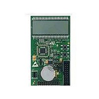
Overview
Power supply (JP1, JP3)
The STM8L15LPBOARD is powered by a lithium battery CR2032 when jumper JP3 is
closed.
Depending on the JP1 position, the MCU consumption auto-measurement circuit can be
used.
Table 1.
LCD glass (R26, C12)
The STM8L15LPBOARD drives a 4-mux LCD glass SBLCDA2. The LCD voltage reference
VLCD is shorted to VDD with a 0 ohm resistor (R26).
The internal LCD voltage reference embedded in the STM8L15LPBOARD can be used
when R26 is removed. R26 is located on the bottom side of the board.
A I µF capacitor C12 is connected to VLCD for internal booster usage.
SWIM connector (CN3)
A SWIM connector CN3 is available for programming and debugging.
Buttons (PC0, PC1)
Two buttons with wakeup interrupt capability are available.
FUNCTION: PC0
WAKEUP:
External quartz (PC5, PC6)
A 32.768 kHz quartz is connected to LSE pins PC5 and PC6. It can be used either as the
RTC clock, or to run the CPU.
JP1 position
1 2 3
1 2 3
JP1 setting
PC1
VDD power is directly connected to MCU VDD when JP1 is set as shown to the left
(default setting).
Note: For manual IDD measurement the JP1 jumper must be removed and replaced
by an ammeter connected between pin 1 and 2 of JP1.
Connect VDD power to MCU with current-sampling resistor (2 ohm or 2 Kohm) in
series for current measurement when JP1 is set as shown to the left.
Doc ID 16160 Rev 2
Description
STM8L15LPBOARD
Related parts for STM8L15LPBOARD
Image
Part Number
Description
Manufacturer
Datasheet
Request
R

Part Number:
Description:
STMicroelectronics [RIPPLE-CARRY BINARY COUNTER/DIVIDERS]
Manufacturer:
STMicroelectronics
Datasheet:
Part Number:
Description:
STMicroelectronics [LIQUID-CRYSTAL DISPLAY DRIVERS]
Manufacturer:
STMicroelectronics
Datasheet:

Part Number:
Description:
BOARD EVAL FOR MEMS SENSORS
Manufacturer:
STMicroelectronics
Datasheet:
Part Number:
Description:
NPN TRANSISTOR POWER MODULE
Manufacturer:
STMicroelectronics
Datasheet:
Part Number:
Description:
TURBOSWITCH ULTRA-FAST HIGH VOLTAGE DIODE
Manufacturer:
STMicroelectronics
Datasheet:
Part Number:
Description:
Manufacturer:
STMicroelectronics
Datasheet:
Part Number:
Description:
DIODE / SCR MODULE
Manufacturer:
STMicroelectronics
Datasheet:
Part Number:
Description:
DIODE / SCR MODULE
Manufacturer:
STMicroelectronics
Datasheet:
Part Number:
Description:
Search -----> STE16N100
Manufacturer:
STMicroelectronics
Datasheet:
Part Number:
Description:
Search ---> STE53NA50
Manufacturer:
STMicroelectronics
Datasheet:
Part Number:
Description:
NPN Transistor Power Module
Manufacturer:
STMicroelectronics
Datasheet:
Part Number:
Description:
DIODE / SCR MODULE
Manufacturer:
STMicroelectronics
Datasheet: