AT91SAM9M10-G45-EK Atmel, AT91SAM9M10-G45-EK Datasheet - Page 12
AT91SAM9M10-G45-EK
Manufacturer Part Number
AT91SAM9M10-G45-EK
Description
KIT EVAL FOR AT91SAMG45/9M10
Manufacturer
Atmel
Series
AT91SAM Smart ARMr
Type
MCUr
Specifications of AT91SAM9M10-G45-EK
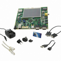
Contents
Board, Cables, Power Supply
Processor To Be Evaluated
AT91SAM9M10
Processor Series
AT91SAM9
Data Bus Width
32 bit
Interface Type
RS-232, Ethernet, USB, JTAG
Operating Supply Voltage
5 V
Silicon Manufacturer
Atmel
Core Architecture
AVR
Kit Contents
Board
Features
Two High Speed USB Hosts, LCD TFT Display
Svhc
No SVHC (15-Dec-2010)
Mcu Supported Families
AT91SAM9M10,
Rohs Compliant
Yes
For Use With/related Products
AT91SAM9M10
Lead Free Status / RoHS Status
Lead free / RoHS Compliant
Available stocks
Company
Part Number
Manufacturer
Quantity
Price
Company:

Part Number:
AT91SAM9M10-G45-EK
Manufacturer:
INFINEON
Quantity:
10 000
Company:
Part Number:
AT91SAM9M10-G45-EK
Manufacturer:
Atmel
Quantity:
135


4.1.4
Figure 4-2.
4.2
4.2.1
AT91SAM9M10-G45-EK User Guide
HEADPHONES
MICROPHONE
JOYSTICK
SD/MMC 0
HEADER
OUTPUT
INPUT
INPUT
VIDEO
USER
SLOT
LINE
Display LCD and LEDs
Hardware Layout and Configuration
Processor
Board Layout Commented
The major components of the SAM9M10-G45-EK board are shown in
The board features the Atmel SAM9M10-CU 324-ball TFBGA package. This chip runs at a nominal fre-
quency of 400 MHz for the core and 133 MHz for the system bus.
For more information, refer to the latest SAM9M10 datasheet available from
VIDEO
HEAD PHONE
JP15
Display, 480xRGBx272 pixels LCD module display connected to the PIO port E (LCD1)
One surface-mounted power red LED, user interface (D3)
Two surface-mounted green LEDs, user interface (D1 and D2)
Three surface-mounted LEDs indicate Ethernet status (D4, D5, D6)
LINE IN
MIC IN
TP2
DBGU
TP4
J20
4
1
Y6
L11
R85
J8
J9
J7
3
DBGU
2
SD/MMC
LCD DISPLAY AREA
Y7
J10
BP3
C143
R183
R181
MN14
L20
R185
1
SELECT
J6
C203
TP6
C149
C148
C156 R84
C155
C133
C199
L8
L9
L12
L10
R80
R79
R83
L17
C198
R73
R78
C137
NANDCS
JP10
J11
MN9
MN11
RS232
NCS0
JP9
RS232
J18
2
1
MN10
MN8
RR13
JP6
RR17
J12
JP5
HOST
4
LCD EXTENSION
USB
VDDIOM1
RR19
TP5
VDDIOM0
CONNECORS
20
19
MN17
C48
2
1
1
LCD EXTENSION
R204
DEVICE
HOST
R203
J14
USB
HOST
HOST
/DEV
R37
C66
1
Q2
Y2
D3
C64
MN6
C38
29
30
C47
ISI
J17
Y1
J1
JTAG
R99
R100
BMS
ICE
JP8
J13
L3
L2
L4
JP1
2
1
MN7
JP2
CONNECTOR
ISI/CAMERA
JP3
J1
40
39
J23
1
4
RR45
C183
Y4
Y5
8
7
ETHERNET
3
2
2
1
MN13
NPCS0
LEFT
C178
D1
C37
R29
VDDBU
C185 R115
3V3
BAT
D2
C176
JP7
5VCC POWER
L5
Figure
R110
SD/MMC+
BP5
C187
C31
R27
JP4
WAKEUP
D4
D5
D6
BP2
RR47
J5
Q1
J2
POWER
MN2
NRST
http://www.atmel.com/
MN1
MN4
BP1
4-1.
RIGHT
BP4
J3
TP3
USER BUTTON
USER BUTTON
Board Description
SD/MMC 1
WAKE-UP
BATTERY
6495B–ATARM–21-Apr-10
BACKUP
«RIGHT»
BUTTON
BUTTON
«LEFT»
RESET
SLOT
4-3
Related parts for AT91SAM9M10-G45-EK
Image
Part Number
Description
Manufacturer
Datasheet
Request
R

Part Number:
Description:
KIT EVAL FOR AT91SAM9M10
Manufacturer:
Atmel
Datasheet:

Part Number:
Description:
IC MCU 16/32BIT ARM9 324TFBGA
Manufacturer:
Atmel
Datasheet:

Part Number:
Description:
At91 Arm Thumb-based Microcontrollers
Manufacturer:
ATMEL Corporation
Datasheet:

Part Number:
Description:
MCU, MPU & DSP Development Tools KICKSTART KIT FOR AT91SAM9 PLUS
Manufacturer:
IAR Systems

Part Number:
Description:
DEV KIT FOR AVR/AVR32
Manufacturer:
Atmel
Datasheet:
Part Number:
Description:
INTERVAL AND WIPE/WASH WIPER CONTROL IC WITH DELAY
Manufacturer:
ATMEL Corporation
Datasheet:
Part Number:
Description:
Low-Voltage Voice-Switched IC for Hands-Free Operation
Manufacturer:
ATMEL Corporation
Datasheet:
Part Number:
Description:
MONOLITHIC INTEGRATED FEATUREPHONE CIRCUIT
Manufacturer:
ATMEL Corporation
Datasheet:
Part Number:
Description:
AM-FM Receiver IC U4255BM-M
Manufacturer:
ATMEL Corporation
Datasheet:
Part Number:
Description:
Monolithic Integrated Feature Phone Circuit
Manufacturer:
ATMEL Corporation
Datasheet:
Part Number:
Description:
Multistandard Video-IF and Quasi Parallel Sound Processing
Manufacturer:
ATMEL Corporation
Datasheet:
Part Number:
Description:
High-performance EE PLD
Manufacturer:
ATMEL Corporation
Datasheet: