ATSTK526 Atmel, ATSTK526 Datasheet - Page 15
ATSTK526
Manufacturer Part Number
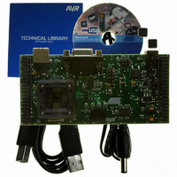
ATSTK526
Description
KIT STARTER FOR AT90USB82/162
Manufacturer
Atmel
Series
AVR®r
Type
MCUr
Specifications of ATSTK526
Contents
Starter Kit Board, Power Supply, Cable and Software
Processor To Be Evaluated
AT90USB82/162
Data Bus Width
8 bit
Interface Type
RS-232, USB
Silicon Manufacturer
Atmel
Core Architecture
AVR
Silicon Core Number
AT90USB82, AT90USB162
Kit Contents
Board Docs
Rohs Compliant
Yes
For Use With/related Products
AT90USB162, AT90USB82
For Use With
ATSTK500 - PROGRAMMER AVR STARTER KIT
Lead Free Status / RoHS Status
Lead free / RoHS Compliant


7709B–AVR–07/08
Using the STK526
2-14
The STK526 USART implementation allows an optional hardware flow control that can
be enabled thanks to SP2, SP3, SP4, SP5 solder pads.
Figure 2-13 . USART Schematic
Note that the USART peripheral of the AT90USB82/162 includes an automatic
Hardware Flow Control feature that makes the operation transparent for the user.
Table 2-3 . UART Settings
Note:
Figure 2-14 . RS232 Solder Pad Location
PD[7..0]
Hardware Flow Control
1. Tx reference: STK526 source, Rx reference: STK526 destination
(default configuration)
Software Data Flow
Optional
Control
Mode
PD2
PD3
PD7
PD6
SP4
SP5
C9
100nF
C10
100nF
RxD
T XD
CT S
RT S
SP4
SP4
SP5
SP5
12
11
10
1
3
4
5
9
U3
C1+
C1-
C2+
C2-
.
.
.
.
TTL
VCC
SP3
SP3
GND
VCC
RS 232
V+
V-
MAX3232
.
.
.
.
Configuration
Solder Pads
RS232 BUFFER
SP2
SP2: close
SP3: close
SP4: close
SP5: close
SP2: open
SP3: open
SP4: open
SP5: open
SP2
2
6
13
14
7
8
100nF
C12
RS-T xD
RS-CT S
RS-RT S
RS-RxD
100nF
STK526 rev. B Hardware User Guide
C11
DECOUPLING CAPACITOR
CLOSE TO THE DEVICE
SP3
SP2
VCC
1
6
2
7
3
8
4
9
5
Connection
P1
SUB-D9 FEMALE
RS232
CTS
RTS
C13
100nF
Rx
Rx
Tx
Tx
DB9
Pin 2
Pin 3
Pin 2
Pin 3
Pin 7
Pin 8
11
10
(1)
Related parts for ATSTK526
Image
Part Number
Description
Manufacturer
Datasheet
Request
R

Part Number:
Description:
DEV KIT FOR AVR/AVR32
Manufacturer:
Atmel
Datasheet:

Part Number:
Description:
INTERVAL AND WIPE/WASH WIPER CONTROL IC WITH DELAY
Manufacturer:
ATMEL Corporation
Datasheet:
Part Number:
Description:
Low-Voltage Voice-Switched IC for Hands-Free Operation
Manufacturer:
ATMEL Corporation
Datasheet:
Part Number:
Description:
MONOLITHIC INTEGRATED FEATUREPHONE CIRCUIT
Manufacturer:
ATMEL Corporation
Datasheet:
Part Number:
Description:
AM-FM Receiver IC U4255BM-M
Manufacturer:
ATMEL Corporation
Datasheet:
Part Number:
Description:
Monolithic Integrated Feature Phone Circuit
Manufacturer:
ATMEL Corporation
Datasheet:
Part Number:
Description:
Multistandard Video-IF and Quasi Parallel Sound Processing
Manufacturer:
ATMEL Corporation
Datasheet:
Part Number:
Description:
High-performance EE PLD
Manufacturer:
ATMEL Corporation
Datasheet:
Part Number:
Description:
8-bit Flash Microcontroller
Manufacturer:
ATMEL Corporation
Datasheet:
Part Number:
Description:
2-Wire Serial EEPROM
Manufacturer:
ATMEL Corporation
Datasheet: