AT89STK-11 Atmel, AT89STK-11 Datasheet - Page 9
AT89STK-11
Manufacturer Part Number
AT89STK-11
Description
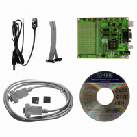
KIT STARTER FOR AT89C51RX2
Manufacturer
Atmel
Type
MCUr
Datasheet
1.AT89STK-11.pdf
(23 pages)
Specifications of AT89STK-11
Contents
Evaluation Board, Software and Documentation
Processor To Be Evaluated
AT89C51Rx
Interface Type
RS-232, SPI, TWI
For Use With/related Products
AT89C51Rx2
Lead Free Status / RoHS Status
Lead free / RoHS Compliant


2.6.5
2.7
2.7.1
2.7.2
AT89STK-11 Hardware User Guide
Expansion Area
Board Settings
Jumpers
Solder Straps
This interface enables the debug of the application through ATMEL OCD dongle for
AT89C51RE2/IE2/RD3/IE3 only.
In addition to a 16x29 pad array, two rows of pads are given on the right side of the
board to offer all the MCU signals tu user application. Any application expansion can be
built on board through this interface.
The C51 Demo Board has the following settings:
The following table provides an overview of the jumpers, the solder straps and their
default configuration.
Table 2-1. Jumpers and Switches Overview
Figure 2-5. Jumper Setting Definition
Solder straps allow to modify the board configuration for specific usage.
Table 2-2. Solder Straps Overview
Reference
Solder strap SP1
Solder strap SP2
Solder strap SP3
Solder strap SP4
Reference
Jumper J11
Jumper J12
Jumper J13
Jumpers
Solder straps
Test points
PCB Label
J11
J12
J13
PCB Label
SP1
ICC
SP3
SP4
Function
RTS of RS232
DTR of RS232
Function
External Power Supply Isolation
Consumption measurement
Rx Led
Tx Led
Hardware Description
Default
OFF
OFF
OFF
Default
Soldered
Soldered
Soldered
Soldered
7676B–8051–08/07
2-8
Related parts for AT89STK-11
Image
Part Number
Description
Manufacturer
Datasheet
Request
R

Part Number:
Description:
KIT EVAL APPL MASS STORAGE
Manufacturer:
Atmel
Datasheet:

Part Number:
Description:
KIT STARTER FOR AT89C5131
Manufacturer:
Atmel
Datasheet:

Part Number:
Description:
KIT DEMOBOARD 8051 MCU W/CAN
Manufacturer:
Atmel
Datasheet:

Part Number:
Description:
KIT STARTER FOR AT83C24
Manufacturer:
Atmel
Datasheet:

Part Number:
Description:
EVAL BOARD FOR AT83C26
Manufacturer:
Atmel
Datasheet:

Part Number:
Description:
KIT STARTER FOR MCU AT8XC5122/23
Manufacturer:
Atmel
Datasheet:


Part Number:
Description:
8-Bit Microcontroller with 4K Bytes Flash
Manufacturer:
ATMEL Corporation
Datasheet:

Part Number:
Description:
DEV KIT FOR AVR/AVR32
Manufacturer:
Atmel
Datasheet:
Part Number:
Description:
INTERVAL AND WIPE/WASH WIPER CONTROL IC WITH DELAY
Manufacturer:
ATMEL Corporation
Datasheet:
Part Number:
Description:
Low-Voltage Voice-Switched IC for Hands-Free Operation
Manufacturer:
ATMEL Corporation
Datasheet:
Part Number:
Description:
MONOLITHIC INTEGRATED FEATUREPHONE CIRCUIT
Manufacturer:
ATMEL Corporation
Datasheet:
Part Number:
Description:
AM-FM Receiver IC U4255BM-M
Manufacturer:
ATMEL Corporation
Datasheet:
Part Number:
Description:
Monolithic Integrated Feature Phone Circuit
Manufacturer:
ATMEL Corporation
Datasheet: