AT89STK-11 Atmel, AT89STK-11 Datasheet - Page 7
AT89STK-11
Manufacturer Part Number
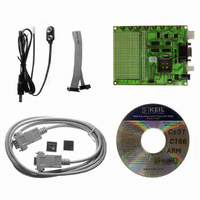
AT89STK-11
Description
KIT STARTER FOR AT89C51RX2
Manufacturer
Atmel
Type
MCUr
Datasheet
1.AT89STK-11.pdf
(23 pages)
Specifications of AT89STK-11
Contents
Evaluation Board, Software and Documentation
Processor To Be Evaluated
AT89C51Rx
Interface Type
RS-232, SPI, TWI
For Use With/related Products
AT89C51Rx2
Lead Free Status / RoHS Status
Lead free / RoHS Compliant


2.3.1.2
2.4
2.4.1
2.4.2
AT89STK-11 Hardware User Guide
External EXT
connector
Reset
Power-on RESET
RESET Push Button
Figure 2-3. Male JACK Outlet and Wires
Note:
Note:
The battery power connector implemented on board is a male two point SIP connector.
It requires an external power cable with a female 2 points connector.
When powered though this interface, polarization is mandatory as no protection is given
on board.
The EXT power supply circuitry support input supply from 2.7V up to 5.5V DC.
Figure 2-4. EXT PWR Female Connector / Cable
Note:
Note:
To be compatible with Atmel microcontrollers which have (or not) its on-chip RESET cir-
cuitry (c.f.microcontroller datasheet), the board provides a RESET signal witch can
come from 2 different sources:
The on-board RC network acts as power-on RESET.
By pressing the RESET push button on the board, a warm RESET of the microcontroller
is performed.
Do not mount more than one power supply source on AT89STK-11 Board.
There is a diode voltage level between the negative output of the power supply
and the “GND”. This could introduce some voltage gap during measurement
and instrumentation.
Do not mount more than one power supply source on board.
Keep SP1 closed when using the EXT input
Hardware Description
7676B–8051–08/07
2-6
Related parts for AT89STK-11
Image
Part Number
Description
Manufacturer
Datasheet
Request
R

Part Number:
Description:
KIT EVAL APPL MASS STORAGE
Manufacturer:
Atmel
Datasheet:

Part Number:
Description:
KIT STARTER FOR AT89C5131
Manufacturer:
Atmel
Datasheet:

Part Number:
Description:
KIT DEMOBOARD 8051 MCU W/CAN
Manufacturer:
Atmel
Datasheet:

Part Number:
Description:
KIT STARTER FOR AT83C24
Manufacturer:
Atmel
Datasheet:

Part Number:
Description:
EVAL BOARD FOR AT83C26
Manufacturer:
Atmel
Datasheet:

Part Number:
Description:
KIT STARTER FOR MCU AT8XC5122/23
Manufacturer:
Atmel
Datasheet:


Part Number:
Description:
8-Bit Microcontroller with 4K Bytes Flash
Manufacturer:
ATMEL Corporation
Datasheet:

Part Number:
Description:
DEV KIT FOR AVR/AVR32
Manufacturer:
Atmel
Datasheet:
Part Number:
Description:
INTERVAL AND WIPE/WASH WIPER CONTROL IC WITH DELAY
Manufacturer:
ATMEL Corporation
Datasheet:
Part Number:
Description:
Low-Voltage Voice-Switched IC for Hands-Free Operation
Manufacturer:
ATMEL Corporation
Datasheet:
Part Number:
Description:
MONOLITHIC INTEGRATED FEATUREPHONE CIRCUIT
Manufacturer:
ATMEL Corporation
Datasheet:
Part Number:
Description:
AM-FM Receiver IC U4255BM-M
Manufacturer:
ATMEL Corporation
Datasheet:
Part Number:
Description:
Monolithic Integrated Feature Phone Circuit
Manufacturer:
ATMEL Corporation
Datasheet: