AT89STK-11 Atmel, AT89STK-11 Datasheet - Page 8
AT89STK-11
Manufacturer Part Number
AT89STK-11
Description
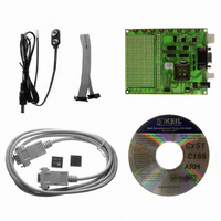
KIT STARTER FOR AT89C51RX2
Manufacturer
Atmel
Type
MCUr
Datasheet
1.AT89STK-11.pdf
(23 pages)
Specifications of AT89STK-11
Contents
Evaluation Board, Software and Documentation
Processor To Be Evaluated
AT89C51Rx
Interface Type
RS-232, SPI, TWI
For Use With/related Products
AT89C51Rx2
Lead Free Status / RoHS Status
Lead free / RoHS Compliant


7676B–8051–08/07
Hardware Description
2.5
2.5.1
2.5.2
2.5.3
2.5.4
2.5.5
2.5.6
2.6
2.6.1
2.6.2
2.6.3
2.6.4
2-7
Features
Push-Buttons
User Push buttons
Indicator LEDs
User LEDs
Ports
Clocks
Interfaces
TWI
SPI
RS-232
OCD
This section presents the various features such as leds, buttons, etc... available on the
board.
They are made available on a 6 pins socket and in the expansion area so user can use
them according to the application needs.
They are made available on a 10 pins socket and in the expansion area so user can use
them according to its application needs.
Port 0 and Port 2 are made available on two 10 pins sockets to ease user interconnec-
tion to the MCU.
The are also available on the expansion area.
An external clock can be connected to the board to control externally XTAL1 input clock
of MCU by using the XTAL1 from the expansion area.
In the same way, another external clock can be connected to control externally the PCA
clock (P1.2/ECI).
The TWI connector is controlled by hardware TWI I/O of MCU (for Product including this
feature). The signals sda and scl are controlled by the TWI ports of MCU.
This TWI bus is also connected to the expansion area.
External TWI pull-ups are not provided on the AT89STK-11.
The SPI connector is directly connected to SPI I/O of the MCU.
The DB9 connector is connected to on-chip UART peripheral through a standard RS232
driver/receiver. Two leds are provided to indicate activity on Rx and Tx lines (They can
be disconnected removing solder pad SP3 and SP4).
The On-Chip Debug interface (OCD) is provided on a 6-pin connector.
RESET can be used to apply warm reset to the MCU
ISP can be used with RESET to apply hardware conditions resulting in bootloader
start
INT0 push-button can be used to activate INT0 input
INT1 push-button can be used to activate INT1 input
PB0, PB1, PB2 and PB3 are four push-buttons available for user application
PWR led is driven by input of voltage regulator
Rx led is connected to Rx of UART MCU (SP3 jumper can be soldered or not)
Tx led is connected to Tx of UART MCU (SP4 jumper can be soldered or not)
ALE led is connected to ALE of MCU
LED0, LED1, ... LED7 are height leds available for user application
AT89STK-11 Hardware User Guide
Related parts for AT89STK-11
Image
Part Number
Description
Manufacturer
Datasheet
Request
R

Part Number:
Description:
KIT EVAL APPL MASS STORAGE
Manufacturer:
Atmel
Datasheet:

Part Number:
Description:
KIT STARTER FOR AT89C5131
Manufacturer:
Atmel
Datasheet:

Part Number:
Description:
KIT DEMOBOARD 8051 MCU W/CAN
Manufacturer:
Atmel
Datasheet:

Part Number:
Description:
KIT STARTER FOR AT83C24
Manufacturer:
Atmel
Datasheet:

Part Number:
Description:
EVAL BOARD FOR AT83C26
Manufacturer:
Atmel
Datasheet:

Part Number:
Description:
KIT STARTER FOR MCU AT8XC5122/23
Manufacturer:
Atmel
Datasheet:


Part Number:
Description:
8-Bit Microcontroller with 4K Bytes Flash
Manufacturer:
ATMEL Corporation
Datasheet:

Part Number:
Description:
DEV KIT FOR AVR/AVR32
Manufacturer:
Atmel
Datasheet:
Part Number:
Description:
INTERVAL AND WIPE/WASH WIPER CONTROL IC WITH DELAY
Manufacturer:
ATMEL Corporation
Datasheet:
Part Number:
Description:
Low-Voltage Voice-Switched IC for Hands-Free Operation
Manufacturer:
ATMEL Corporation
Datasheet:
Part Number:
Description:
MONOLITHIC INTEGRATED FEATUREPHONE CIRCUIT
Manufacturer:
ATMEL Corporation
Datasheet:
Part Number:
Description:
AM-FM Receiver IC U4255BM-M
Manufacturer:
ATMEL Corporation
Datasheet:
Part Number:
Description:
Monolithic Integrated Feature Phone Circuit
Manufacturer:
ATMEL Corporation
Datasheet: