HW-SD1800A-DSP-SB-UNI-G Xilinx Inc, HW-SD1800A-DSP-SB-UNI-G Datasheet - Page 31
HW-SD1800A-DSP-SB-UNI-G
Manufacturer Part Number
HW-SD1800A-DSP-SB-UNI-G
Description
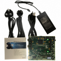
KIT DEVELOPMENT SPARTAN 3ADSP
Manufacturer
Xilinx Inc
Series
Spartan™-3A DSPr
Type
DSPr
Datasheet
1.HW-SD1800A-DSP-SB-UNI-G.pdf
(38 pages)
Specifications of HW-SD1800A-DSP-SB-UNI-G
Contents
Development Platform, Power Supply and software
Silicon Manufacturer
Xilinx
Features
10/100/1000 PHY, JTAG Programming And Configuration Port
Silicon Family Name
Spartan-3A
Silicon Core Number
3SD1800A-FG676
Lead Free Status / RoHS Status
Lead free / RoHS Compliant
For Use With/related Products
Spartan 3A
Lead Free Status / RoHS Status
Lead free / RoHS Compliant, Lead free / RoHS Compliant
Other names
122-1574
HW-SD1800A-DSP-DB-UNI-G
HW-SD1800A-DSP-DB-UNI-G
HW-SD1800A-DSP-SB-UNI-G
HW-SD1800A-DSP-DB-UNI-G
HW-SD1800A-DSP-DB-UNI-G
HW-SD1800A-DSP-SB-UNI-G
Available stocks
Company
Part Number
Manufacturer
Quantity
Price


Spartan-3A DSP Starter Platform User Guide
UG454 (v1.1) January 30, 2009
R
consequently, PI filters on the output of each of the PTH05050WAZ and PTH04000WAZ are
utilized to minimize these transients.
X-Ref Target - Figure 11
Based on measurements during prototyping, the PTH04000 circuit for 1.2V was tuned to
increase the output voltage slightly. The voltage measured at the FPGA was observed to be
about 20mV low. Therefore, the set resistor for the PTH04000 was modified based on the
calculations provided in the TI data sheet to raise the voltage by 20mV. Nominally, resistor
R42 should be 26.1K, but on this board it is 24.3K.
The DDR2 0.9V reference and termination voltages (FPGA_DDR2_VREF, FPGA_0.9V_TT)
and the 1.8V power rail for the DDR2 memory and the DP83865 Ethernet PHY core voltage
are provided by a switching power supply designed around the Texas Instruments
TPS51116 Synchronous Buck Controller. The +1.2V, +2.5V and +3.3V power rails are
monitored to provide an active-low reset condition (PO_RESET#) until these rails are
above their threshold settings. A pushbutton switch (SW4) may be used to manually create
the PO_RESET# condition. LED D6 is lit when PO_RESET# is driven active. LEDs D16, D17
and D18 are lit to show the presence of +1.2V, +2.5V and P3.3V, respectively.
Current measurements of the various power rails may be taken by removing the shunts on
jumpers JP10 (+3.3V), JP14 (+2.5V), JP6 (+1.8V), and JP5 (+1.2V), and placing an ammeter
across the pins. Note that these jumpers are 2x2 requiring two shunts each in order top
provide enough current-carrying capacity so the user should ensure that both shunts are in
place for normal operation.
The user may experiment with the Spartan-3A DSP low-power SUSPEND mode by
jumpering JP11 pins 2:3 (default 1:2). The AWAKE LED (D15) indicates the SUSPEND
mode status.
www.xilinx.com
Figure 11: Application of Power
UG454_11_050908
Board Power
55
Related parts for HW-SD1800A-DSP-SB-UNI-G
Image
Part Number
Description
Manufacturer
Datasheet
Request
R

Part Number:
Description:
KIT DEVELOPMENT SPARTAN 3ADSP
Manufacturer:
Xilinx Inc

Part Number:
Description:
IC CPLD .8K 36MCELL 44-VQFP
Manufacturer:
Xilinx Inc
Datasheet:

Part Number:
Description:
IC CPLD 72MCRCELL 10NS 44VQFP
Manufacturer:
Xilinx Inc
Datasheet:

Part Number:
Description:
IC CPLD 1.6K 72MCELL 64-VQFP
Manufacturer:
Xilinx Inc
Datasheet:

Part Number:
Description:
IC CR-II CPLD 64MCELL 44-VQFP
Manufacturer:
Xilinx Inc
Datasheet:

Part Number:
Description:
IC CPLD 1.6K 72MCELL 100-TQFP
Manufacturer:
Xilinx Inc
Datasheet:

Part Number:
Description:
IC CR-II CPLD 64MCELL 56-BGA
Manufacturer:
Xilinx Inc
Datasheet:

Part Number:
Description:
IC CPLD 72MCRCELL 7.5NS 44VQFP
Manufacturer:
Xilinx Inc
Datasheet:
Part Number:
Description:
IC CR-II CPLD 64MCELL 100-VQFP
Manufacturer:
Xilinx Inc
Datasheet:
Part Number:
Description:
IC CPLD 1.6K 72MCELL 100-TQFP
Manufacturer:
Xilinx Inc
Datasheet:

Part Number:
Description:
IC CPLD 72MCRCELL 7.5NS 64VQFP
Manufacturer:
Xilinx Inc
Datasheet:
Part Number:
Description:
IC CPLD 1.6K 72MCELL 100-TQFP
Manufacturer:
Xilinx Inc
Datasheet:

Part Number:
Description:
IC CPLD 1.5K 64MCELL HP 44-VQFP
Manufacturer:
Xilinx Inc

Part Number:
Description:
IC CPLD 36MCRCELL 15NS 44PLCC
Manufacturer:
Xilinx Inc
Datasheet:

Part Number:
Description:
IC CPLD 36MCRCELL 10NS 44PLCC
Manufacturer:
Xilinx Inc
Datasheet: