AT91SAM9XE-EK Atmel, AT91SAM9XE-EK Datasheet - Page 22
AT91SAM9XE-EK
Manufacturer Part Number
AT91SAM9XE-EK
Description
KIT EVAL FOR AT91SAM9XE
Manufacturer
Atmel
Type
MCUr
Datasheet
1.AT91SAM9XE-EK.pdf
(34 pages)
Specifications of AT91SAM9XE-EK
Contents
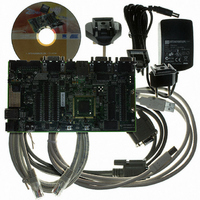
Evaluation Board, Power Supply with adapters, Cables and software
Processor To Be Evaluated
AT91SAM9XE
Data Bus Width
32 bit
Interface Type
RS-232, Ethernet, USB
Core
ARM
Operating Supply Voltage
5 V
Kit Contents
Board Cable Power Supply CD
Supported Devices
AT91SAM9XE
Tool / Board Applications
General Purpose MCU, MPU, DSP, DSC
Development Tool Type
Hardware / Software - Eval/Demo Board
Rohs Compliant
Yes
Mcu Supported Families
AT91SAM
For Use With/related Products
AT91SAM9XE
Lead Free Status / RoHS Status
Lead free / RoHS Compliant
Available stocks
Company
Part Number
Manufacturer
Quantity
Price
Company:

Part Number:
AT91SAM9XE-EK
Manufacturer:
Atmel
Quantity:
135


4.5
4.6
AT91SAM9XE-EK Evaluation Board User Guide
Ethernet
Miscellaneous
RMII is the factory default mode.
To evaluate the MII mode, the user has to unsolder R49, R50, R127, close S7, S8 and populate R119 to
R126, C88, C89, Y4.
Refer to the TOP level schematic for the PIO usage.
Table 4-5. Miscellaneous
Designation
R101
R103
R104
R105
R106
R82
R72
R73
R94
R95
R96
R98
R83
R85
R86
R88
TP1
TP2
TP3
TP4
TP5
TP6
Default Setting
Soldered
Soldered
Soldered
Soldered
Soldered
Soldered
Soldered
N.A
N.A
N.A
N.A
N.A
N.A
USB DEVICE: Enables the use of the USBCNX signal
DBGU COM Port: Enables the use of DTXD output signal.
Enables the use of DRXD input.
RS232 COM Port 0: Enable the use of output signals.
RTS0
TXD0
DTR0
RS232 COM Port 0: Enable the use of input signals.
DCD0
DSR0
RXD0
CTS0
RI0
Enables all MAX3241E outputs buffer
RS232 COM Port 1: Enables the use of output signals.
TXD1
RTS1
RS232 COM Port 1: Enables the use of input signals.
RXD1
CTS1
GND Test point
GND Test point.
GND Test point.
GND Test point.
Reserved: do not use
Reserved: do not use
Feature
6311A–ATARM–04-Feb-08
4-3
Related parts for AT91SAM9XE-EK
Image
Part Number
Description
Manufacturer
Datasheet
Request
R

Part Number:
Description:
MCU, MPU & DSP Development Tools KICKSTART KIT FOR AT91SAM9 PLUS
Manufacturer:
IAR Systems

Part Number:
Description:
MCU ARM9 64K SRAM 144-LFBGA
Manufacturer:
Atmel
Datasheet:

Part Number:
Description:
IC ARM7 MCU FLASH 256K 100LQFP
Manufacturer:
Atmel
Datasheet:

Part Number:
Description:
IC ARM9 MPU 217-LFBGA
Manufacturer:
Atmel
Datasheet:
Part Number:
Description:
MCU ARM9 ULTRA LOW PWR 217-LFBGA
Manufacturer:
Atmel
Datasheet:

Part Number:
Description:
MCU ARM9 324-TFBGA
Manufacturer:
Atmel
Datasheet:
Part Number:
Description:
IC MCU ARM9 SAMPLING 217CBGA
Manufacturer:
Atmel
Datasheet:
Part Number:
Description:
IC ARM9 MCU 217-LFBGA
Manufacturer:
Atmel
Datasheet:

Part Number:
Description:
IC ARM9 MCU 208-PQFP
Manufacturer:
Atmel
Datasheet:
Part Number:
Description:
MCU ARM 512K HS FLASH 100-LQFP
Manufacturer:
Atmel
Datasheet:

Part Number:
Description:
MCU ARM 512K HS FLASH 100-TFBGA
Manufacturer:
Atmel
Datasheet:
Part Number:
Description:
IC ARM9 MCU 200 MHZ 324-TFBGA
Manufacturer:
Atmel
Datasheet:

Part Number:
Description:
IC ARM MCU 16BIT 128K 256BGA
Manufacturer:
Atmel
Datasheet:

Part Number:
Description:
IC ARM7 MCU 32BIT 128K 64LQFP
Manufacturer:
Atmel
Datasheet:

Part Number:
Description:
IC ARM7 MCU FLASH 256K 128-LQFP
Manufacturer:
Atmel
Datasheet: