AT91SAM9G20-EK Atmel, AT91SAM9G20-EK Datasheet - Page 25
AT91SAM9G20-EK
Manufacturer Part Number
AT91SAM9G20-EK
Description
KIT EVAL FOR AT91SAM9G20 MCU
Manufacturer
Atmel
Type
MCUr
Datasheet
1.AT91SAM9G20-EK.pdf
(39 pages)
Specifications of AT91SAM9G20-EK
Contents
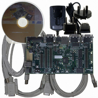
Board, Cables, CD, Power Supply
Processor To Be Evaluated
AT91SAM9G20
Data Bus Width
32 bit
Interface Type
RS-232, Ethernet, USB
Core
RISC
Silicon Manufacturer
Atmel
Core Architecture
ARM
Core Sub-architecture
ARM926EJ-S
Silicon Core Number
AT91SAM9G20
Silicon Family Name
ARM
Kit Contents
Board CD Docs
Rohs Compliant
Yes
For Use With/related Products
AT91SAM9G20
Lead Free Status / RoHS Status
Lead free / RoHS Compliant
Available stocks
Company
Part Number
Manufacturer
Quantity
Price
Company:

Part Number:
AT91SAM9G20-EK
Manufacturer:
Atmel
Quantity:
135


4.5
4.6
AT91SAM9G20-EK Evaluation Board User Guide
Ethernet
Miscellaneous
RMII is the factory default mode. To evaluate the MII mode, the user has to unsolder R49, R50, R127
and close S7 and S8. When the RMII mode is used, the user can use the specific MII signals as PIO, but
the following resistors must be unsoldered (R119 to R126).
Note that, by default, resistors R112 and R120 are not populated in order to avoid contention between
the MII signals and the SD Card slot J35. If the Ethernet MII mode is implemented on the board, then you
must not insert any card into slot J35. Otherwise, signal conflicts could occur and damage both the
Ethernet controller and the SD Card.
Refer to “Board Layout - Top View” in
Section 5.1 ”Schematics”
for the PIO Usage.
6413C–ATARM–18-Feb-09
Configuration
4-3
Related parts for AT91SAM9G20-EK
Image
Part Number
Description
Manufacturer
Datasheet
Request
R

Part Number:
Description:
MCU, MPU & DSP Development Tools KICKSTART KIT FOR AT91SAM9 PLUS
Manufacturer:
IAR Systems

Part Number:
Description:
DEV KIT FOR AVR/AVR32
Manufacturer:
Atmel
Datasheet:

Part Number:
Description:
INTERVAL AND WIPE/WASH WIPER CONTROL IC WITH DELAY
Manufacturer:
ATMEL Corporation
Datasheet:
Part Number:
Description:
Low-Voltage Voice-Switched IC for Hands-Free Operation
Manufacturer:
ATMEL Corporation
Datasheet:
Part Number:
Description:
MONOLITHIC INTEGRATED FEATUREPHONE CIRCUIT
Manufacturer:
ATMEL Corporation
Datasheet:
Part Number:
Description:
AM-FM Receiver IC U4255BM-M
Manufacturer:
ATMEL Corporation
Datasheet:
Part Number:
Description:
Monolithic Integrated Feature Phone Circuit
Manufacturer:
ATMEL Corporation
Datasheet:
Part Number:
Description:
Multistandard Video-IF and Quasi Parallel Sound Processing
Manufacturer:
ATMEL Corporation
Datasheet:
Part Number:
Description:
High-performance EE PLD
Manufacturer:
ATMEL Corporation
Datasheet:
Part Number:
Description:
8-bit Flash Microcontroller
Manufacturer:
ATMEL Corporation
Datasheet:
Part Number:
Description:
2-Wire Serial EEPROM
Manufacturer:
ATMEL Corporation
Datasheet: