AT91SAM7SE-EK Atmel, AT91SAM7SE-EK Datasheet - Page 12
AT91SAM7SE-EK
Manufacturer Part Number
AT91SAM7SE-EK
Description
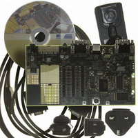
EVAL BOARD FOR AT91SAM7SE
Manufacturer
Atmel
Series
AT91SAM Smart ARMr
Type
MCUr
Datasheet
1.AT91SAM7SE-EK.pdf
(36 pages)
Specifications of AT91SAM7SE-EK
Contents
Evaluation Board, Parallel Cable and CD-ROM
Processor To Be Evaluated
AT91SAM7SE
Data Bus Width
32 bit
Interface Type
RS-232, USB
Silicon Manufacturer
Atmel
Core Architecture
ARM
Core Sub-architecture
ARM7TDMI
Silicon Core Number
AT91SAM7SE
Silicon Family Name
ARM
Kit Contents
Board CD Docs
Rohs Compliant
Yes
For Use With/related Products
AT91SAM7SE
Lead Free Status / RoHS Status
Lead free / RoHS Compliant


6241B–ATARM–22-Mar-07
Board Description
3-2
• Advanced Interrupt Controller (AIC)
• Debug Unit (DBGU)
• Periodic Interval Timer (PIT)
• Windowed Watchdog (WDT)
• Real-time Timer (RTT)
• Three Parallel Input/Output Controllers (PIO)
• Eleven Peripheral DMA Controller (PDC) Channels
• One USB 2.0 Full Speed (12 Mbits per second) Device Port
• One Synchronous Serial Controller (SSC)
• Two Universal Synchronous/Asynchronous Receiver Transmitters (USART)
• One Master/Slave Serial Peripheral Interfaces (SPI)
• One Three-channel 16-bit Timer/Counter (TC)
• One Four-channel 16-bit PWM Controller (PWMC)
• One Two-wire Interface (TWI)
• One 8-channel 10-bit Analog-to-Digital Converter, Four Channels Multiplexed with
• SAM-BA
Digital I/Os
– Power Optimization Capabilities, Including Slow Clock Mode (Down to 500 Hz)
– Three Programmable External Clock Signals
– Individually Maskable, Eight-level Priority, Vectored Interrupt Sources
– Two External Interrupt Sources and One Fast Interrupt Source, Spurious Interrupt
– Two-wire UART and Support for Debug Communication Channel interrupt,
– 20-bit Programmable Counter plus 12-bit Interval Counter
– 12-bit key-protected Programmable Counter
– Provides Reset or Interrupt Signals to the System
– Counter May Be Stopped While the Processor is in Debug State or in Idle Mode
– 32-bit Free-running Counter with Alarm
– Runs Off the Internal RC Oscillator
– Eighty-eight Programmable I/O Lines Multiplexed with up to Two Peripheral I/Os
– Input Change Interrupt Capability on Each I/O Line
– Individually Programmable Open-drain, Pull-up Resistor and Synchronous Output
– Schmitt Trigger on All inputs
– On-chip Transceiver, Eight Endpoints, 2688-byte Configurable Integrated FIFOs
– Independent Clock and Frame Sync Signals for Each Receiver and Transmitter
– I²S Analog Interface Support, Time Division Multiplex Support
– High-speed Continuous Data Stream Capabilities with 32-bit Data Transfer
– Individual Baud Rate Generator, IrDA
– Support for ISO7816 T0/T1 Smart Card, Hardware Handshaking, RS485 Support
– Full Modem Line Support on USART1
– 8- to 16-bit Programmable Data Length, Four External Peripheral Chip Selects
– Three External Clock Inputs, Two Multi-purpose I/O Pins per Channel
– Double PWM Generation, Capture/Waveform Mode, Up/Down Capability
– Master, Multi-Master and Slave Mode Support, All Two-wire Atmel EEPROMs
– General Call Supported in Slave Mode
– Default Boot program
– Interface with SAM-BA Graphic User Interface
and Idle Mode
Protected
Programmable ICE Access Prevention
Supported
™
AT91SAM7SE-EK Evaluation Board User Guide
®
Infrared Modulation/Demodulation
Related parts for AT91SAM7SE-EK
Image
Part Number
Description
Manufacturer
Datasheet
Request
R

Part Number:
Description:
MCU ARM9 64K SRAM 144-LFBGA
Manufacturer:
Atmel
Datasheet:

Part Number:
Description:
IC ARM7 MCU FLASH 256K 100LQFP
Manufacturer:
Atmel
Datasheet:

Part Number:
Description:
IC ARM9 MPU 217-LFBGA
Manufacturer:
Atmel
Datasheet:
Part Number:
Description:
MCU ARM9 ULTRA LOW PWR 217-LFBGA
Manufacturer:
Atmel
Datasheet:

Part Number:
Description:
MCU ARM9 324-TFBGA
Manufacturer:
Atmel
Datasheet:
Part Number:
Description:
IC MCU ARM9 SAMPLING 217CBGA
Manufacturer:
Atmel
Datasheet:
Part Number:
Description:
IC ARM9 MCU 217-LFBGA
Manufacturer:
Atmel
Datasheet:

Part Number:
Description:
IC ARM9 MCU 208-PQFP
Manufacturer:
Atmel
Datasheet:
Part Number:
Description:
MCU ARM 512K HS FLASH 100-LQFP
Manufacturer:
Atmel
Datasheet:

Part Number:
Description:
MCU ARM 512K HS FLASH 100-TFBGA
Manufacturer:
Atmel
Datasheet:
Part Number:
Description:
IC ARM9 MCU 200 MHZ 324-TFBGA
Manufacturer:
Atmel
Datasheet:

Part Number:
Description:
IC ARM MCU 16BIT 128K 256BGA
Manufacturer:
Atmel
Datasheet:

Part Number:
Description:
IC ARM7 MCU 32BIT 128K 64LQFP
Manufacturer:
Atmel
Datasheet:

Part Number:
Description:
IC ARM7 MCU FLASH 256K 128-LQFP
Manufacturer:
Atmel
Datasheet:
Part Number:
Description:
IC ARM7 MCU FLASH 512K 128-LQFP
Manufacturer:
Atmel
Datasheet: