DM300018 Microchip Technology, DM300018 Datasheet - Page 25
DM300018
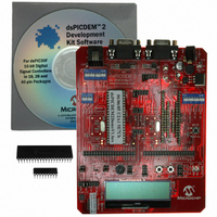
Manufacturer Part Number
DM300018
Description
BOARD DEMO DSPICDEM 2
Manufacturer
Microchip Technology
Type
MCUr
Specifications of DM300018
Contents
*
Processor To Be Evaluated
dsPIC30F
Interface Type
RS-232
Silicon Manufacturer
Microchip
Core Architecture
DsPIC
Core Sub-architecture
DsPIC30
Silicon Core Number
DsPIC30F
Silicon Family Name
DsPIC30F2xxx, DsPIC30F3xxx
Lead Free Status / RoHS Status
Not applicable / RoHS Compliant
For Use With/related Products
dsPIC30F
Lead Free Status / Rohs Status
Lead free / RoHS Compliant
Other names
Q2448034
Available stocks
Company
Part Number
Manufacturer
Quantity
Price
Company:

Part Number:
DM300018
Manufacturer:
MICROCHIP
Quantity:
12 000


2.6
© 2005 Microchip Technology Inc.
IN-CIRCUIT DEBUGGING PROCESS
2.5.3
1. Select Project>Build All .
2. Observe the progress of the build in the Output window.
3. When BUILD SUCCEEDED displays you are ready to program the device.
4. Program the dsPIC30F4011device ( Programmer>Program )
2.5.4
1. From the Programmer menu, select Release from Reset to enable code
2. On the board, turn off the M ALL switch in S2.
3. As the code begins executing, note that the operation is identical to what you
MPLAB IDE lets you run, halt and step the program. It lets you set breakpoints to
examine the code at specific locations or on occurrence of specific events. It also lets
you examine the contents of the RAM and registers. The MPLAB ICD 2 allows you to
run the application on the dsPICDEM 2 while monitoring it in MPLAB IDE on your PC.
The examination process requires that three changes be made to the sample
application setup.
• The dsPIC30F4011 device must be reprogrammed to recognize the MPLAB ICD
• MPLAB IDE must be reconfigured to specify the pins on the dsPIC30F device to
• The dsPICDEM 2 board must be physically reconfigured to ensure that it connects
2.6.1
To change MPLAB ICD 2 from a programmer to a debugger for a dsPIC30F4011
device:
1. From the Debugger menu, click Select Tool>MPLAB ICD 2 to designate the
2. From the Configure menu, select Configuration Bits... The Configuration Bits
3. Change the “Comm Channel Select” parameter to Use EMUC2 and EMUD2.
4. On the dsPICDEM 2 board, change the setting on switch S3 to turn on EMUC2
5. Program the dsPIC30F device ( Debugger>Program menu).
6. On the dsPICDEM 2 board, turn off M ALL on switch S2.
7. Reset the program and run it. From the Debugger menu, select Reset>Processor
2 as a debugger rather than as a programmer.
be used for debugging.
the MPLAB ICD 2 debugger to the pins on the dsPIC30F device that were
specified in MPLAB IDE.
Note:
exectution .
observed out-of-the-box (see Section 2.4.3 “Observe Sample Application”)
MPLAB ICD 2 as the debug tool in MPLAB IDE.
window displays the current configuration settings for the device, as shown in
Figure 2-7.
and EMUD2.
Reset . Then select Debugger>Run .
Build the Project
Run the Application
Select MPLAB ICD 2 as Debugger
The primary programming and debugging functions (PGC/EMUC,
PGD/EMUD) on the dsPIC30F device are multiplexed with other peripheral
modules on the device used by the sample application. Thus it is necessary
to use an alternate pair of debugging pins (EMUC1/EMUD1,
EMUC2/EMUD2 or EMUC3/EMUD3) to examine the baseline code
provided in the sample application.
Getting Started
DS51558A-page 19
Related parts for DM300018
Image
Part Number
Description
Manufacturer
Datasheet
Request
R

Part Number:
Description:
Manufacturer:
Microchip Technology Inc.
Datasheet:
Part Number:
Description:
Manufacturer:
Microchip Technology Inc.
Datasheet:
Part Number:
Description:
Manufacturer:
Microchip Technology Inc.
Datasheet:
Part Number:
Description:
Manufacturer:
Microchip Technology Inc.
Datasheet:
Part Number:
Description:
Manufacturer:
Microchip Technology Inc.
Datasheet:
Part Number:
Description:
Manufacturer:
Microchip Technology Inc.
Datasheet:
Part Number:
Description:
Manufacturer:
Microchip Technology Inc.
Datasheet:
Part Number:
Description:
Manufacturer:
Microchip Technology Inc.
Datasheet: