DM300018 Microchip Technology, DM300018 Datasheet - Page 17
DM300018
Manufacturer Part Number
DM300018
Description
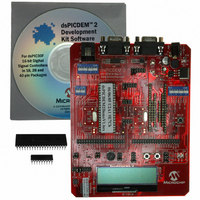
BOARD DEMO DSPICDEM 2
Manufacturer
Microchip Technology
Type
MCUr
Specifications of DM300018
Contents
*
Processor To Be Evaluated
dsPIC30F
Interface Type
RS-232
Silicon Manufacturer
Microchip
Core Architecture
DsPIC
Core Sub-architecture
DsPIC30
Silicon Core Number
DsPIC30F
Silicon Family Name
DsPIC30F2xxx, DsPIC30F3xxx
Lead Free Status / RoHS Status
Not applicable / RoHS Compliant
For Use With/related Products
dsPIC30F
Lead Free Status / Rohs Status
Lead free / RoHS Compliant
Other names
Q2448034
Available stocks
Company
Part Number
Manufacturer
Quantity
Price
Company:

Part Number:
DM300018
Manufacturer:
MICROCHIP
Quantity:
12 000


© 2005 Microchip Technology Inc.
1.4.6
This pushbutton switch (S1) is tied to the MCLR pin on the dsPIC30F device. It is used
to reset the device regardless of the socket used.
1.4.7
Device clocking can be provided by on-chip RC oscillators, on-board crystal oscillators
or external sources. Crystal (Y1) provides a 7.3728 MHz oscillator for the motor control
device. Crystal (Y2) provides a 7.3728 MHz oscillator for the general purpose and
sensor devices.
1.4.8
The dsPICDEM™ 2 provides the following sensors that can be used to provide input
signals to your application program:
• Temperature sensor (U5)
• Potentiometer (R15)
• Pushbutton switches (S5 and S6)
1.4.8.1
The temperature sensor is a TC1047A that provides an analog signal to analog
channel AN3 in either the general purpose or motor control device via header H10.
1.4.8.2
A 5-kOhm potentiometer provides an analog signal to analog channel AN2 in either the
general purpose or motor control device via header H13. The voltage source to the
potentiometer is provided by VR1, through a low-pass filter. VR1 is the main voltage
regulator for all components on the development board.
1.4.8.3
Two pushbutton switches, S5 and S6, are connected to external interrupt pins INT0 and
INT1, respectively, on the dsPIC30F device via headers H6 and H7, respectively.
1.4.9
The dsPICDEM™ 2 provides the following output devices that can be used to display
output information from your application program:
• LED Indicators (D3 and D4)
• LCD Display (LCD1/LCD2)
1.4.9.1
LEDs D3 and D4 are connected to port pins RB0 and RB1, respectively on the installed
dsPIC DSC device via header H12. The LED anodes are tied to VDD through a 1.2K
resistor.
1.4.9.2
A 2 x 16 character dot matrix LCD display is provided on the development board. The
installed dsPIC30F device writes characters to the LCD via the clock (SCK1) and data
(SDO1) pins on the device’s SPI1 module.
1.4.10
Prototyping areas H8 and H9 provide external connections from the motor control and
general purpose devices, respectively. These connections allow you to use hardware
and test equipment not provided on the dsPICDEM™ 2 board.
Reset Switch
Device Clocking
Analog and Digital Inputs
TEMPERATURE SENSOR
ANALOG POTENTIOMETER
PUSHBUTTON SWITCHES
Digital Outputs
LED INDICATORS
LCD DISPLAY
External Connections
Introduction
DS51558A-page 11
Related parts for DM300018
Image
Part Number
Description
Manufacturer
Datasheet
Request
R

Part Number:
Description:
Manufacturer:
Microchip Technology Inc.
Datasheet:
Part Number:
Description:
Manufacturer:
Microchip Technology Inc.
Datasheet:
Part Number:
Description:
Manufacturer:
Microchip Technology Inc.
Datasheet:
Part Number:
Description:
Manufacturer:
Microchip Technology Inc.
Datasheet:
Part Number:
Description:
Manufacturer:
Microchip Technology Inc.
Datasheet:
Part Number:
Description:
Manufacturer:
Microchip Technology Inc.
Datasheet:
Part Number:
Description:
Manufacturer:
Microchip Technology Inc.
Datasheet:
Part Number:
Description:
Manufacturer:
Microchip Technology Inc.
Datasheet: