SCA3100-D04 PCB VTI Technologies, SCA3100-D04 PCB Datasheet - Page 8
SCA3100-D04 PCB
Manufacturer Part Number
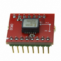
SCA3100-D04 PCB
Description
EVAL BOARD ACCELEROMETER 3-AXIS
Manufacturer
VTI Technologies
Specifications of SCA3100-D04 PCB
Sensor Type
Accelerometer, 3 Axis
Sensing Range
±2g
Interface
SPI
Sensitivity
900 counts/g
Voltage - Supply
3 V ~ 3.6 V
Embedded
No
Utilized Ic / Part
SCA3100-D04
Lead Free Status / RoHS Status
Lead free / RoHS Compliant
Other names
551-1061


2.2.1.1
2.2.1.2
2.2.1.3
2.2.2
2.2.2.1
VTI Technologies Oy
www.vti.fi
Usage
Bypass measurement mode
Narrow band measurement mode
Wide band measurement mode
Overflow condition
Table
In bypass measurement mode, the signal bandwidth of the SCA3000 is extended by bypassing the
low-pass filter in signal channel. As a result of a wider measurement bandwidth, the noise level is
higher.
In narrow band measurement mode, the signal bandwidth of the SCA3000 is reduced by increasing
low-pass filtering in signal channel. In addition, the output data rate is halved due to decimation. As
a result of a narrower signal bandwidth, the noise level is lower.
In wide band measurement mode, the SCA3000 signal channel low-pass filtering pass band is
widened. As a result of a wider measurement bandwidth, the noise level is higher.
The optional measurement modes can be enabled by setting the bits called MODE_BITS in MODE
register to "010" or "001". See section 3.4 for MODE register details.
Acceleration data can be read from data output registers X_LSB, X_MSB, Y_LSB, Y_MSB, Z_LSB
and Z_MSB in all measurement modes. Each of these registers can be read one by one or using
the decrement register read, which is described in section 4.1.3.2 for SPI and 4.2.1.3 for I
interface. See section 3.3 for output register details.
Since acceleration data registers have no limiter, the possible overflow needs to be detected using
bits [B7, B6, B5]. If bits [B7, B6, B5] are ‘011’ or ‘100’, data overflow has occurred (see Table 3).
This applies for all acceleration output registers (X_LSB … Z_MSB and BUF_DATA).
Table 3. Overflow bit patterns in acceleration data registers (X_LSB … Z_MSB and BUF_DATA).
Byte
Bit number
Acceleration data bit
Data overflow on
positive acceleration
Data overflow on
negative
acceleration
x = ignore
In case of overflow, the output register value must be discarded. When an overflow is detected, the
bit pattern ‘0101 1111 1111 1xxx’ is used for positive accelerations and ‘1010 0000 0000 0xxx’ for
Available measurement
modes
Default after power-on
or reset
Optional measurement
mode 1
Optional measurement
mode 2
2.
Available measurement modes for SCA3000.
MSB byte
Sign
B7
SCA3000-D01
SCA3000-D02
Measurement
mode
Bypass
measurement
mode
Not available
0
1
Doc.Nr. 8257300A.07
d11
B6
1
0
d10
B5
1
0
B4
SCA3000-E01
SCA3000-E02
Measurement
mode
Narrow band
measurement
mode
Not available
d9
x
x
B3
d8
x
x
B2
d7
x
x
B1
SCA3000-E04
Measurement
mode
Narrow band
measurement
mode
Wide band
measurement
mode
d6
x
x
B0
d5
x
x
LSB byte
B7
d4
x
x
SCA3000-E05
Measurement
mode
Narrow band
measurement
mode
Wide band
measurement
mode
B6
d3
x
x
B5
d2
x
x
B4
d1
x
x
SCA3000 Series
B3
d0
x
x
B2:B0
Rev.A.07
xxx
xxx
8/ 43
2
C
Related parts for SCA3100-D04 PCB
Image
Part Number
Description
Manufacturer
Datasheet
Request
R

Part Number:
Description:
KIT DEMO ACCELEROMETER SCA3100
Manufacturer:
VTI Technologies
Datasheet:

Part Number:
Description:
ACCELEROMETER 3-AXIS +/-6G SPI
Manufacturer:
VTI Technologies
Datasheet:

Part Number:
Description:
ACCELEROMETER 3-AXIS +/-2G SPI
Manufacturer:
VTI Technologies
Datasheet:

Part Number:
Description:
ACCELEROMETER SGL 1.7G DIL8 SMD
Manufacturer:
VTI Technologies
Datasheet:

Part Number:
Description:
VTI Automotive Digital Accelerometer Platform
Manufacturer:
VTI [VTI technologies]
Datasheet:

Part Number:
Description:
BOARD PWB ACCEL 3-AXIS SPI/I2C
Manufacturer:
VTI Technologies
Datasheet:

Part Number:
Description:
EVAL BOARD ACCELEROMETER Y-AXIS
Manufacturer:
VTI Technologies
Datasheet:

Part Number:
Description:
EVAL BOARD INCLINOMETER Y-AXIS
Manufacturer:
VTI Technologies
Datasheet:

Part Number:
Description:
KIT DEMO ACCELEROMTR CMA3000-D01
Manufacturer:
VTI Technologies
Datasheet:

Part Number:
Description:
DEMO KIT WITH SCC1300-D04
Manufacturer:
VTI Technologies
Datasheet:
Part Number:
Description:
ACCELEROMETER SGL 1.7G DIL8 SMD
Manufacturer:
VTI Technologies
Datasheet:
Part Number:
Description:
VTI Automotive Digital Accelerometer Platform
Manufacturer:
VTI [VTI technologies]
Datasheet:
Part Number:
Description:
Accelerometer
Manufacturer:
VTI [VTI technologies]
Datasheet:
Part Number:
Description:
Stand Alone Inclinometer
Manufacturer:
VTI [VTI technologies]
Datasheet:
Part Number:
Description:
3-axis accelerometer
Manufacturer:
VTI [VTI technologies]
Datasheet: