EVAL-ADXL345Z-DB Analog Devices Inc, EVAL-ADXL345Z-DB Datasheet - Page 29
EVAL-ADXL345Z-DB
Manufacturer Part Number
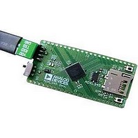
EVAL-ADXL345Z-DB
Description
BOARD EVAL FOR ADXL345
Manufacturer
Analog Devices Inc
Series
iMEMS®r
Datasheets
1.EVAL-ADXL345Z.pdf
(40 pages)
2.EVAL-ADXL345Z.pdf
(2 pages)
3.EVAL-ADXL345Z.pdf
(12 pages)
Specifications of EVAL-ADXL345Z-DB
Sensor Type
Accelerometer, 3 Axis
Sensing Range
±2g, 4g, 8g, 16g
Interface
I²C, SPI
Sensitivity
256LSB/g, 128LSB/g, 64LSB/g, 32LSB/g
Voltage - Supply
2 V ~ 3.6 V
Embedded
No
Utilized Ic / Part
ADXL345
Silicon Manufacturer
Analog Devices
Application Sub Type
Accelerometer - Three-Axis
Kit Application Type
Sensing - Motion / Vibration / Shock
Silicon Core Number
ADXL345
Lead Free Status / RoHS Status
Lead free / RoHS Compliant


Several events can occur to invalidate the second tap of a double
tap event. First, if the suppress bit in the TAP_AXES register
(Address 0x2A) is set, any acceleration spike above the threshold
during the latency time (set by the latent register) invalidates
the double tap detection, as shown in Figure 46.
A double tap event can also be invalidated if acceleration above
the threshold is detected at the start of the time window for the
second tap (set by the window register). This results in an invalid
double tap at the start of this window, as shown in Figure 47.
Additionally, a double tap event can be invalidated if an accel-
eration exceeds the time limit for taps (set by the DUR register),
resulting in an invalid double tap at the end of the DUR time
limit for the second tap event, also shown in Figure 47.
TIME LIMIT
TIME LIMIT
FOR TAPS
FOR TAPS
(DUR)
(DUR)
Figure 47. Tap Interrupt Function with Invalid Double Taps
Figure 46. Double Tap Event Invalid Due to High g Event
LATENCY
(LATENT)
TIME (LATENT)
TIME
LATENCY
When the Suppress Bit Is Set
DOUBLE TAP AT
INVALIDATES
END OF DUR
TIME LIMIT
FOR TAPS
(DUR)
SECOND TAP (WINDOW)
TIME LIMIT
FOR TAPS
TIME WINDOW FOR
INVALIDATES DOUBLE TAP IF
TIME WINDOW FOR SECOND
(DUR)
INVALIDATES DOUBLE TAP
AT START OF WINDOW
SUPRESS BIT SET
TAP (WINDOW)
Rev. B | Page 29 of 40
Single taps, double taps, or both can be detected by setting the
respective bits in the INT_ENABLE register (Address 0x2E).
Control over participation of each of the three axes in single tap/
double tap detection is exerted by setting the appropriate bits in
the TAP_AXES register (Address 0x2A). For the double tap
function to operate, both the latent and window registers must
be set to a nonzero value.
Every mechanical system has somewhat different single tap/
double tap responses based on the mechanical characteristics of
the system. Therefore, some experimentation with values for the
DUR, latent, window, and THRESH_TAP registers is required.
In general, a good starting point is to set the DUR register to a
value greater than 0x10 (10 ms), the latent register to a value greater
than 0x10 (20 ms), the window register to a value greater than
0x40 (80 ms), and the THRESH_TAP register to a value greater
than 0x30 (3 g). Setting a very low value in the latent, window, or
THRESH_TAP register may result in an unpredictable response
due to the accelerometer picking up echoes of the tap inputs.
After a tap interrupt has been received, the first axis to exceed
the THRESH_TAP level is reported in the ACT_TAP_STATUS
register (Address 0x2B). This register is never cleared but is
overwritten with new data.
THRESHOLD
The lower output data rates are achieved by decimating a common
sampling frequency inside the device. The activity, free-fall, and
single tap/double tap detection functions without improved tap
enabled are performed using undecimated data. Because the
bandwidth of the output data varies with the data rate and is
lower than the bandwidth of the undecimated data, the high
frequency and high g data that is used to determine activity,
free-fall, and single tap/double tap events may not be present
if the output of the accelerometer is examined. This may result
in functions triggering when acceleration data does not appear
to meet the conditions set by the user for the corresponding
function.
LINK MODE
The function of the link bit is to reduce the number of activity
interrupts that the processor must service by setting the device
to look for activity only after inactivity. For proper operation of
this feature, the processor must still respond to the activity and
inactivity interrupts by reading the INT_SOURCE register
(Address 0x30) and, therefore, clearing the interrupts. If an activity
interrupt is not cleared, the part cannot go into autosleep mode.
The asleep bit in the ACT_TAP_STATUS register (Address 0x2B)
indicates if the part is asleep.
ADXL345
Related parts for EVAL-ADXL345Z-DB
Image
Part Number
Description
Manufacturer
Datasheet
Request
R

Part Number:
Description:
IC, ADJ LDO REG, 1.5V TO 5V 250mA MSOP-8
Manufacturer:
Vishay
Datasheet:

Part Number:
Description:
IC, ADJ LDO REG, 1.5V TO 5V 0.6A 8-TSSOP
Manufacturer:
Vishay
Datasheet:
Part Number:
Description:
IC, ADJ LDO REG, 1.5V TO 5V 250mA MSOP-8
Manufacturer:
Vishay
Datasheet:

Part Number:
Description:
IC ADJ LDO REG 1.5V TO 5V 150mA 5-SOT-23
Manufacturer:
Vishay
Datasheet:

Part Number:
Description:
BOARD EVAL AS1324-AD
Manufacturer:
austriamicrosystems
Datasheet:
Part Number:
Description:
IC, ADJ LDO REG, 1.5V TO 5V 0.6A 8-TSSOP
Manufacturer:
Vishay
Datasheet:

Part Number:
Description:
IC, ADJ LDO REG, 1.5V TO 5V, 0.3A, MSOP8
Manufacturer:
Vishay
Datasheet:
Part Number:
Description:
IC, ADJ LDO REG, 1.5V TO 5V, 0.3A, MSOP8
Manufacturer:
Vishay
Datasheet:
Part Number:
Description:
IC, ADJ LDO REG 1.215V TO 5V 0.3A MSOP-8
Manufacturer:
Vishay
Datasheet:
Part Number:
Description:
IC, ADJ LDO REG 1.215V TO 5V 0.3A MSOP-8
Manufacturer:
Vishay
Datasheet:

Part Number:
Description:
±1.7g Dual-Axis IMEMS Accelerometer Evaluation Board
Manufacturer:
Analog Devices Inc
Datasheet:

Part Number:
Description:
IC MULTIPLIER ANALOG 8-SOIC T/R
Manufacturer:
Analog Devices Inc
Datasheet:

Part Number:
Description:
IC ANALOG MULTIPLIER 8-DIP
Manufacturer:
Analog Devices Inc
Datasheet:
Part Number:
Description:
IC ANALOG MULTIPLIER 8-SOIC
Manufacturer:
Analog Devices Inc
Datasheet:
Part Number:
Description:
IC ANALOG MULTIPLIER 8-DIP
Manufacturer:
Analog Devices Inc
Datasheet: