EVAL-ADXL345Z-DB Analog Devices Inc, EVAL-ADXL345Z-DB Datasheet - Page 27
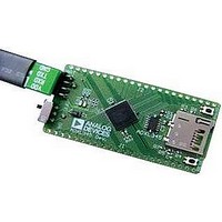
EVAL-ADXL345Z-DB
Manufacturer Part Number
EVAL-ADXL345Z-DB
Description
BOARD EVAL FOR ADXL345
Manufacturer
Analog Devices Inc
Series
iMEMS®r
Datasheets
1.EVAL-ADXL345Z.pdf
(40 pages)
2.EVAL-ADXL345Z.pdf
(2 pages)
3.EVAL-ADXL345Z.pdf
(12 pages)
Specifications of EVAL-ADXL345Z-DB
Sensor Type
Accelerometer, 3 Axis
Sensing Range
±2g, 4g, 8g, 16g
Interface
I²C, SPI
Sensitivity
256LSB/g, 128LSB/g, 64LSB/g, 32LSB/g
Voltage - Supply
2 V ~ 3.6 V
Embedded
No
Utilized Ic / Part
ADXL345
Silicon Manufacturer
Analog Devices
Application Sub Type
Accelerometer - Three-Axis
Kit Application Type
Sensing - Motion / Vibration / Shock
Silicon Core Number
ADXL345
Lead Free Status / RoHS Status
Lead free / RoHS Compliant


INT_INVERT Bit
A value of 0 in the INT_INVERT bit sets the interrupts to active
high, and a value of 1 sets the interrupts to active low.
FULL_RES Bit
When this bit is set to a value of 1, the device is in full resolution
mode, where the output resolution increases with the g range
set by the range bits to maintain a 4 mg/LSB scale factor. When
the FULL_RES bit is set to 0, the device is in 10-bit mode, and
the range bits determine the maximum g range and scale factor.
Justify Bit
A setting of 1 in the justify bit selects left-justified (MSB) mode,
and a setting of 0 selects right-justified mode with sign extension.
Range Bits
These bits set the g range as described in Table 21.
Table 21. g Range Setting
D1
0
0
1
1
Register 0x32 to Register 0x37—DATAX0, DATAX1,
DATAY0, DATAY1, DATAZ0, DATAZ1 (Read Only)
These six bytes (Register 0x32 to Register 0x37) are eight bits
each and hold the output data for each axis. Register 0x32 and
Register 0x33 hold the output data for the x-axis, Register 0x34 and
Register 0x35 hold the output data for the y-axis, and Register 0x36
and Register 0x37 hold the output data for the z-axis. The output
data is twos complement, with DATAx0 as the least significant
byte and DATAx1 as the most significant byte, where x represent X,
Y, or Z. The DATA_FORMAT register (Address 0x31) controls
the format of the data. It is recommended that a multiple-byte
read of all registers be performed to prevent a change in data
between reads of sequential registers.
Register 0x38—FIFO_CTL (Read/Write)
D7
FIFO_MODE
FIFO_MODE Bits
These bits set the FIFO mode, as described in Table 22.
Setting
D6
D0
0
1
0
1
D5
Trigger
g Range
±2 g
±4 g
±8 g
±16 g
D4
D3
Samples
D2
D1
D0
Rev. B | Page 27 of 40
Table 22. FIFO Modes
D7
0
0
1
1
Trigger Bit
A value of 0 in the trigger bit links the trigger event of trigger mode
to INT1, and a value of 1 links the trigger event to INT2.
Samples Bits
The function of these bits depends on the FIFO mode selected
(see Table 23). Entering a value of 0 in the samples bits immediately
sets the watermark status bit in the INT_SOURCE register,
regardless of which FIFO mode is selected. Undesirable operation
may occur if a value of 0 is used for the samples bits when trigger
mode is used.
Table 23. Samples Bits Functions
FIFO Mode
Bypass
FIFO
Stream
Trigger
0x39—FIFO_STATUS (Read Only)
D7
FIFO_TRIG
FIFO_TRIG Bit
A 1 in the FIFO_TRIG bit corresponds to a trigger event occurring,
and a 0 means that a FIFO trigger event has not occurred.
Entries Bits
These bits report how many data values are stored in FIFO.
Access to collect the data from FIFO is provided through the
DATAX, DATAY, and DATAZ registers. FIFO reads must be
done in burst or multiple-byte mode because each FIFO level is
cleared after any read (single- or multiple-byte) of FIFO. FIFO
stores a maximum of 32 entries, which equates to a maximum
of 33 entries available at any given time because an additional
entry is available at the output filter of the device.
Setting
D6
0
1
0
1
Mode
Bypass
FIFO
Stream
Trigger
Samples Bits Function
None.
Specifies how many FIFO entries are needed to
trigger a watermark interrupt.
Specifies how many FIFO entries are needed to
trigger a watermark interrupt.
Specifies how many FIFO samples are retained in
the FIFO buffer before a trigger event.
D6
0
Function
FIFO is bypassed.
FIFO collects up to 32 values and then
stops collecting data, collecting new data
only when FIFO is not full.
FIFO holds the last 32 data values. When
FIFO is full, the oldest data is overwritten
with newer data.
When triggered by the trigger bit, FIFO
holds the last data samples before the
trigger event and then continues to collect
data until full. New data is collected only
when FIFO is not full.
D5
D4
D3
Entries
D2
ADXL345
D1
D0
Related parts for EVAL-ADXL345Z-DB
Image
Part Number
Description
Manufacturer
Datasheet
Request
R

Part Number:
Description:
IC, ADJ LDO REG, 1.5V TO 5V 250mA MSOP-8
Manufacturer:
Vishay
Datasheet:

Part Number:
Description:
IC, ADJ LDO REG, 1.5V TO 5V 0.6A 8-TSSOP
Manufacturer:
Vishay
Datasheet:
Part Number:
Description:
IC, ADJ LDO REG, 1.5V TO 5V 250mA MSOP-8
Manufacturer:
Vishay
Datasheet:

Part Number:
Description:
IC ADJ LDO REG 1.5V TO 5V 150mA 5-SOT-23
Manufacturer:
Vishay
Datasheet:

Part Number:
Description:
BOARD EVAL AS1324-AD
Manufacturer:
austriamicrosystems
Datasheet:
Part Number:
Description:
IC, ADJ LDO REG, 1.5V TO 5V 0.6A 8-TSSOP
Manufacturer:
Vishay
Datasheet:

Part Number:
Description:
IC, ADJ LDO REG, 1.5V TO 5V, 0.3A, MSOP8
Manufacturer:
Vishay
Datasheet:
Part Number:
Description:
IC, ADJ LDO REG, 1.5V TO 5V, 0.3A, MSOP8
Manufacturer:
Vishay
Datasheet:
Part Number:
Description:
IC, ADJ LDO REG 1.215V TO 5V 0.3A MSOP-8
Manufacturer:
Vishay
Datasheet:
Part Number:
Description:
IC, ADJ LDO REG 1.215V TO 5V 0.3A MSOP-8
Manufacturer:
Vishay
Datasheet:

Part Number:
Description:
±1.7g Dual-Axis IMEMS Accelerometer Evaluation Board
Manufacturer:
Analog Devices Inc
Datasheet:

Part Number:
Description:
IC MULTIPLIER ANALOG 8-SOIC T/R
Manufacturer:
Analog Devices Inc
Datasheet:

Part Number:
Description:
IC ANALOG MULTIPLIER 8-DIP
Manufacturer:
Analog Devices Inc
Datasheet:
Part Number:
Description:
IC ANALOG MULTIPLIER 8-SOIC
Manufacturer:
Analog Devices Inc
Datasheet:
Part Number:
Description:
IC ANALOG MULTIPLIER 8-DIP
Manufacturer:
Analog Devices Inc
Datasheet: