MCP9700DM-TH1 Microchip Technology, MCP9700DM-TH1 Datasheet - Page 14
MCP9700DM-TH1
Manufacturer Part Number
MCP9700DM-TH1
Description
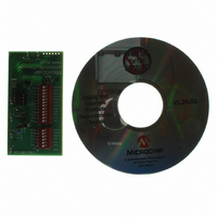
BOARD DEMO THERMISTOR MCP9700
Manufacturer
Microchip Technology
Datasheets
1.MCP9700DM-PCTL.pdf
(24 pages)
2.MCP9700DM-TH1.pdf
(24 pages)
3.MCP9701AT-ELT.pdf
(20 pages)
Specifications of MCP9700DM-TH1
Sensor Type
Temperature
Sensing Range
-40°C ~ 125°C
Interface
Analog
Sensitivity
±1°C
Voltage - Supply
2.3 V ~ 5.5 V
Embedded
Yes, MCU, 8-Bit
Utilized Ic / Part
MCP6S22, MCP9700
Lead Free Status / RoHS Status
Lead free / RoHS Compliant


MCP9700 Thermistor Demo Board User’s Guide
DS51753A-page 10
Each resistor with its switch (in SW1) pointing to the right, away from the silk screen
resistor values, is not added into the total for R
Each resistor with its switch (in SW1) pointing to the left, towards the silk screen resistor
values, is added into the total for R
As an example, if the top four switches are to the right, and the bottom two are to the
left, then R
2.3.3
In Appendix A. “Schematic and Layouts”, R
The resistance changes depending on temperature; see AN897, “Thermistor
Temperature Sensing with MCP6SX2 PGAs” (DS00897).
2.3.4
DIP switch SW2 and resistors R
(Rvar in
409.5 kΩ.
Refer to
FIGURE 2-5:
Each resistor with its switch (in SW2) pointing to the right, away from the silk screen
resistor values, is not added into the total for R
Each resistor with its switch (in SW) pointing to the left, towards the silk screen resistor
values, is added into the total for R
As an example, if the top ten switches are to the right, and the bottom two are to the
left, then Rvar is calculated as 0 + 0 + ... + 0 + 102,400 + 204,800 = 307,200Ω.
AN897, “Thermistor Temperature Sensing with MCP6SX2 PGAs” (DS00897) contains
information on converting this resistance to the equivalent, nominal thermistor
temperature, and vice versa.
2.3.5
The MCP9700 Linear Active Thermistor is a temperature sensor which outputs voltage
directly proportional to change in temperature. This sensor provides a 10 mV per
degree Celsius temperature coefficient and it measures temperature from -40
+125
°
C, see datasheet (DS21942) for details.
Figure
Figure A.3
Using the Thermistor (R
Configuring DIP Switch SW2 (R
Using the MCP9700
A
is calculated as 500 + 0 + 0 + 0 + 0 + 8,000 + 16,000 = 24,500Ω.
2-3). Rvar produces a binary sequence of resistances between 0Ω and
102,400
204,800
12,800
25,600
51,200
1,600
3,200
6,400
for the complete schematic.
100
200
400
800
R
TH
Emulator (Rvar).
SW2
8
– R
A
A
.
.
19
TH
in Figure 2-5 comprise the thermistor emulator
)
21
A
A
TH
(it shorts that resistor).
(it shorts that resistor).
is the thermistor (R
Emulator, Rvar)
R8
R9
R10 402Ω
R11 806Ω
R12 1.6 kΩ
R13 3.24 kΩ
R14 6.49 kΩ
R15 12.7 kΩ
R16 25.5 kΩ
R17 51.1 kΩ
R18 102 kΩ
R19 205 kΩ
© 2008 Microchip Technology Inc.
100Ω
200Ω
TH
in
Figure
°
C to
2-3).
Related parts for MCP9700DM-TH1
Image
Part Number
Description
Manufacturer
Datasheet
Request
R

Part Number:
Description:
IC SENSOR THERMAL 2.30 TO-92-3
Manufacturer:
Microchip Technology
Datasheet:

Part Number:
Description:
Low-Power Linear Active Thermistor� ICs
Manufacturer:
MICROCHIP [Microchip Technology]
Datasheet:
Part Number:
Description:
Low-Power Voltage output temperature sensor
Manufacturer:
Microchip Technology, Inc.
Datasheet:
Part Number:
Description:
Low-power Linear Active Thermistor
Manufacturer:
Microchip Technology, Inc.

Part Number:
Description:
(MCP9700 / MCP9701) Low-Power Voltage Output Temperature Sensor
Manufacturer:
Microchip Technology
Datasheet:

Part Number:
Description:
Manufacturer:
Microchip Technology Inc.
Datasheet:
Part Number:
Description:
Manufacturer:
Microchip Technology Inc.
Datasheet:
Part Number:
Description:
Manufacturer:
Microchip Technology Inc.
Datasheet:
Part Number:
Description:
Manufacturer:
Microchip Technology Inc.
Datasheet:
Part Number:
Description:
Manufacturer:
Microchip Technology Inc.
Datasheet:
Part Number:
Description:
Manufacturer:
Microchip Technology Inc.
Datasheet: