MCP9700DM-TH1 Microchip Technology, MCP9700DM-TH1 Datasheet
MCP9700DM-TH1
Specifications of MCP9700DM-TH1


Related parts for MCP9700DM-TH1


MCP9700DM-TH1 Summary of contents
Page 1
... Microchip Technology Inc. MCP9700 Thermistor Demo Board User’s Guide DS51753A ...
Page 2
... PowerMate, PowerTool, REAL ICE, rfLAB, Select Mode, Total Endurance, UNI/O, WiperLock and ZENA are trademarks of Microchip Technology Incorporated in the U.S.A. and other countries. SQTP is a service mark of Microchip Technology Incorporated in the U.S.A. All other trademarks mentioned herein are property of their respective companies. ...
Page 3
... A.3 Board - Top Silk-screen Layer ..................................................................... 15 A.4 Board - Top Layer ........................................................................................ 15 A.5 Board - Bottom Silk ...................................................................................... 16 A.6 Board - Bottom Layer ................................................................................... 16 Appendix B. Bill Of Materials (BOM) Worldwide Sales and Service .................................................................................... 20 © 2008 Microchip Technology Inc. MCP9700 THERMISTOR DEMO BOARD USER’S GUIDE Table of Contents DS51753A-page iii ...
Page 4
... MCP9700 Thermistor Demo Board User’s Guide NOTES: DS51753A-page iv © 2008 Microchip Technology Inc. ...
Page 5
... Appendix A. “Schematic and Layouts” – Shows the schematic and layout diagrams for the MCP9700 Thermistor Demo Board. • Appendix B. “Bill Of Materials (BOM)” – Lists the parts used to build the MCP9700 Thermistor Demo Board. © 2008 Microchip Technology Inc. MCP9700 THERMISTOR DEMO BOARD USER’S GUIDE Preface NOTICE TO CUSTOMERS ® ...
Page 6
... Optional arguments mcc18 [options] file [options] Choice of mutually exclusive errorlevel {0|1} arguments selection Replaces repeated text var_name [, var_name...] Represents code supplied by void main (void) user { ... } © 2008 Microchip Technology Inc. Examples ® IDE User’s Guide ...
Page 7
... Customers should contact their distributor, representative or field application engineer for support. Local sales offices are also available to help customers. A listing of sales offices and locations is included in the back of this document. Technical support is available through the web site at: http://support.microchip.com © 2008 Microchip Technology Inc. Preface DS51753A-page 3 ...
Page 8
... MCP9700 Thermistor Demo Board User’s Guide DOCUMENT REVISION HISTORY Revision A (August 2008) • Initial Release of this Document DS51753A-page 4 © 2008 Microchip Technology Inc. ...
Page 9
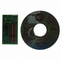
... MCP9700 Thermistor Demo Board – An assembled and tested PCB (102-00156) • Microchip Thermal Management Graphical User Interface • Analog and Interface Products Demonstration Boards CD-ROM (DS21912) - MCP9700 Thermistor Demo Board User's Guide, (DS51753) © 2008 Microchip Technology Inc. MCP9700 THERMISTOR DEMO BOARD USER’S GUIDE ® ...
Page 10
... MCP9700 Thermistor Demo Board User’s Guide NOTES: DS51753A-page 6 © 2008 Microchip Technology Inc. ...
Page 11
... PC. The MCP9700 Thermistor Demo Board is fully powered and temperature can be measured. 2. Start the Thermal Management Software GUI for data logging or to evaluate the MCP9700 Thermistor Demo Board features. © 2008 Microchip Technology Inc. MCP9700 THERMISTOR DEMO BOARD USER’S GUIDE Figure 2-1 ...
Page 12
... The user can compare and evaluate both the standard thermistor solution and Microchip’s Linear Active Thermistor solution using this MCP9700 Thermistor Demo Board. DS51753A-page 8 Thermistor Voltage Divider MCP6S22 PGA PIC18F2550 MCP9700 MCP9700 Thermistor Demo Board Circuit Block Diagram. USB Interface PC © 2008 Microchip Technology Inc. ...
Page 13
... Configuring DIP Switch SW1 (R DIP switch Figure 2-3 together. These resistors produce a binary sequence of values between 0.5 kΩ and 32.0 kΩ. Refer to Figure A.3 FIGURE 2-4: © 2008 Microchip Technology Inc. Installation and Operation 5. filter and PGA’s CH0 input JMP1 Rvar R TH Simplified Jumper Circuit ...
Page 14
... Emulator, Rvar) R8 100Ω R9 200Ω R10 402Ω R11 806Ω R12 1.6 kΩ R13 3.24 kΩ R14 6.49 kΩ R15 12.7 kΩ R16 25.5 kΩ R17 51.1 kΩ R18 102 kΩ R19 205 kΩ ° © 2008 Microchip Technology Inc. ...
Page 15
... The Real-time Data Acquisition charting tool can be customized by double clicking the chart, as shown in chart. The users can also zoom into a specific plot range by clicking and dragging the section. FIGURE 2-7: © 2008 Microchip Technology Inc. Installation and Operation Figure 2-6. Microchip Thermal Management GUI. ...
Page 16
... MCP9700 Thermistor Demo Board User’s Guide NOTES: DS51753A-page 12 © 2008 Microchip Technology Inc. ...
Page 17
... This appendix contains the following schematics and layouts for the MCP9700 Thermistor Demo Board: • Board Schematic • Board - Top Layer • Board - Silk-screen Layer • Board - Bottom Layer © 2008 Microchip Technology Inc. MCP9700 THERMISTOR DEMO BOARD USER’S GUIDE DS51753A-page 13 ...
Page 18
... MCP9700 Thermistor Demo Board User’s Guide A.2 BOARD SCHEMATIC - PAGE 1 DS51753A-page 14 © 2008 Microchip Technology Inc. ...
Page 19
... A.3 BOARD - TOP SILK-SCREEN LAYER A.4 BOARD - TOP LAYER © 2008 Microchip Technology Inc. Schematic and Layouts DS51753A-page 15 ...
Page 20
... MCP9700 Thermistor Demo Board User’s Guide A.5 BOARD - BOTTOM SILK A.6 BOARD - BOTTOM LAYER DS51753A-page 16 © 2008 Microchip Technology Inc. ...
Page 21
... RES 10.0 OHM 1/8W 1% 0805 SMD Panasonic - ECG Note: The components listed in this Bill of Materials are representative of the PCB assembly. The released BOM used in manufacturing uses all RoHS-compliant components. © 2008 Microchip Technology Inc. MCP9700 THERMISTOR DEMO BOARD USER’S GUIDE Description Manufacturer ® ...
Page 22
... Description Manufacturer Panasonic - ECG Panasonic - ECG Grayhill, Inc Grayhill, Inc Microchip Technology Inc. PIC18F2550-I/SO Microchip Technology Inc. MCP6S22-I/P Microchip Technology Inc. MCP9700-E/TO CTS-Frequency Controls Part Number ERJ-6ENF1001V ERJ-6ENF2001V ERJ-6ENF4021V ERJ-6ENF8061V ERJ-6ENF1622V ERJ-6ENF1000V ERJ-6ENF2000V 78B06ST 78B12ST ATS200SM © 2008 Microchip Technology Inc. ...
Page 23
... NOTES: © 2008 Microchip Technology Inc. Bill Of Materials (BOM) DS51753A-page 19 ...
Page 24
... Fax: 886-3-572-6459 Taiwan - Kaohsiung Tel: 886-7-536-4818 Fax: 886-7-536-4803 Taiwan - Taipei Tel: 886-2-2500-6610 Fax: 886-2-2508-0102 Thailand - Bangkok Tel: 66-2-694-1351 Fax: 66-2-694-1350 © 2008 Microchip Technology Inc. EUROPE Austria - Wels Tel: 43-7242-2244-39 Fax: 43-7242-2244-393 Denmark - Copenhagen Tel: 45-4450-2828 Fax: 45-4485-2829 France - Paris Tel: 33-1-69-53-63-20 ...