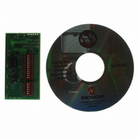
MCP9700DM-TH1 Microchip Technology, MCP9700DM-TH1 Datasheet - Page 13

MCP9700DM-TH1
Manufacturer Part Number
MCP9700DM-TH1
Description
BOARD DEMO THERMISTOR MCP9700
Manufacturer
Microchip Technology
Datasheets
1.MCP9700DM-PCTL.pdf
(24 pages)
2.MCP9700DM-TH1.pdf
(24 pages)
3.MCP9701AT-ELT.pdf
(20 pages)
Specifications of MCP9700DM-TH1
Sensor Type
Temperature
Sensing Range
-40°C ~ 125°C
Interface
Analog
Sensitivity
±1°C
Voltage - Supply
2.3 V ~ 5.5 V
Embedded
Yes, MCU, 8-Bit
Utilized Ic / Part
MCP6S22, MCP9700
Lead Free Status / RoHS Status
Lead free / RoHS Compliant
2.3
© 2008 Microchip Technology Inc.
CONFIGURING BOARD
2.3.1
Figure 2-3
the right side of jumper JMP1, the thermistor R
on the left side of jumper JMP1, the thermistor emulator Rvar is connected to the circuit.
Refer to Figure A.3 for the complete schematic.
FIGURE 2-3:
2.3.2
DIP switch SW
(R
together. These resistors produce a binary sequence of values between 0.5 kΩ and
32.0 kΩ.
Refer to
FIGURE 2-4:
A
in
Figure
Figure A.3
Configuring Jumper JMP1 (select Thermistor or Rvar)
Configuring DIP Switch SW1 (R
shows how jumper JMP1 configures the circuit. When the shorting bar is on
2-3). R
1
and resistors R
for the complete schematic.
Rvar
1
Simplified Jumper Circuit.
16,000
R
is placed in series with the others to prevent shorting the supplies
1,000
2,000
4,000
8,000
A
500
500
R
Emulator.
A
JMP1
V
R
DD
1
TH
SW
– R
= 5.0V
1
Installation and Operation
7
in
+5V
To filter and PGA’s CH0 input
Figure 2-4
R
499
1
TH
A
is connected to the circuit. When it is
)
emulate the voltage divider resistor
R2 499Ω
R3 1.00 kΩ
R4 2.00 kΩ
R5 4.02 kΩ
R6 8.06 kΩ
R7 16.0 kΩ
DS51753A-page 9


