STEVAL-MKI024V1 STMicroelectronics, STEVAL-MKI024V1 Datasheet - Page 29
STEVAL-MKI024V1
Manufacturer Part Number
STEVAL-MKI024V1
Description
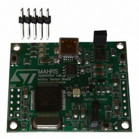
DEMO BOARD BASED ON LIS331DL
Manufacturer
STMicroelectronics
Series
MEMSr
Datasheets
1.STEVAL-MKI024V1.pdf
(42 pages)
2.STEVAL-MKI024V1.pdf
(39 pages)
3.STEVAL-MKI024V1.pdf
(4 pages)
Specifications of STEVAL-MKI024V1
Design Resources
STEVAL-MKI024V1 Gerber Files STEVAL-MKI024V1 Schematics STEVAL-MKI024V1 Bill of Materials
Sensor Type
Accelerometer, 3 Axis
Sensing Range
±2.3g, 9.2g
Interface
SPI, USB
Sensitivity
72mg/digit
Voltage - Supply
5V, USB
Embedded
Yes, MCU, 8-Bit
Utilized Ic / Part
LIS331DL
Acceleration
2 g, 8 g
Sensing Axis
Triple Axis
Output Type
Digital
Interface Type
USB
Silicon Manufacturer
ST Micro
Silicon Core Number
LIS331DL
Kit Application Type
Sensing - Motion / Vibration / Shock
Application Sub Type
Accelerometer
Kit Contents
Board
Lead Free Status / RoHS Status
Lead free / RoHS Compliant
Other names
497-8719
Available stocks
Company
Part Number
Manufacturer
Quantity
Price
Company:

Part Number:
STEVAL-MKI024V1
Manufacturer:
STMicroelectronics
Quantity:
135


UM0692
Note:
7.2.1
7.2.2
7.2.3
7.2.4
Table 1.
AA: register address
DD: data
S: service field
X, Y, Z: Acceleration data returned for the X, Y and Z axes
I1, I2 : interrupt value on each axis.
Start command
The *start command initiates the continuous data acquisition. When this command is sent to
the board, it returns the acceleration data measured by the LIS331DL device. The
acceleration data are packed in a string composed of eight bytes: “
two bytes are always “s” and “t” which correspond to the hexadecimal values {73 74}, while
“X” “Y” “Z” represent, respectively, the acceleration data for the X, Y, Z axes.
“I1” and “I2” contain the values of FF_WU_SRC1 and FF_WU_SRC2, where each bit is a
specific interrupt.
The last byte “s” returns information about the switches mounted on the board. Specifically,
bit#1 and bit#0 of the "service data" correspond to the status of SW3 and SW2 on the
demonstration kit board, and they are set to 1 when the corresponding switch is pressed.
Debug command
The debug command starts the continuous data acquisition in debug mode. When this
command is sent to the board, it returns the acceleration data measured by the LIS331DL
device in readable text format. The values shown on the screen correspond to the content of
the output data registers and are shown as a decimal number. A tab is employed as a
separator between the different fields.
Stop command
The *stop command interrupts any acquisition session that has been started with either the
*start or *debug commands.
Register read
The *rAA command allows the contents of the LIS331DL device registers in the
demonstration kit board to be read. AA, expressed as hexadecimal value and written upper-
case, represents the address of the register to be read.
*bwAA<0:7><0|1>
Command
*wAADD
*Zon
*Zoff
*dev
*ver
Supported commands (continued)
Firmware version
Exit from 3-state
Single bit write
Register write
Force 3-state
Device name
Description
s t x y z I1 I2 s
Supported commands
Returned value
331DL 1.0
LIS331DL
”. The first
29/39
Related parts for STEVAL-MKI024V1
Image
Part Number
Description
Manufacturer
Datasheet
Request
R

Part Number:
Description:
BOARD EVAL FOR MEMS SENSORS
Manufacturer:
STMicroelectronics
Datasheet:

Part Number:
Description:
EVALBOARD/STEVAL-ISV014V1
Manufacturer:
STMicroelectronics
Part Number:
Description:
BOARD EVAL FOR ST802RT1
Manufacturer:
STMicroelectronics
Datasheet:

Part Number:
Description:
BOARD EVAL FOR VACUUM CLEANER
Manufacturer:
STMicroelectronics
Datasheet:

Part Number:
Description:
KIT DEV STARTER ST10F276Z5
Manufacturer:
STMicroelectronics
Datasheet:

Part Number:
Description:
BOARD LED CTLR/DVR STLED316S
Manufacturer:
STMicroelectronics
Datasheet:

Part Number:
Description:
BOARD EVAL BLDC SENSORLESS MOTOR
Manufacturer:
STMicroelectronics
Datasheet:

Part Number:
Description:
BOARD ELECT FISCAL CASH REGISTER
Manufacturer:
STMicroelectronics
Datasheet:

Part Number:
Description:
BOARD EVAL BIPO SOLUTION FOR PFC
Manufacturer:
STMicroelectronics
Datasheet:

Part Number:
Description:
BOARD EVAL UPS 450W VOUT=220V
Manufacturer:
STMicroelectronics
Datasheet:
Part Number:
Description:
STMicroelectronics [RIPPLE-CARRY BINARY COUNTER/DIVIDERS]
Manufacturer:
STMicroelectronics
Datasheet:
Part Number:
Description:
STMicroelectronics [LIQUID-CRYSTAL DISPLAY DRIVERS]
Manufacturer:
STMicroelectronics
Datasheet:
Part Number:
Description:
BOARD EVAL FOR MEMS SENSORS
Manufacturer:
STMicroelectronics
Datasheet: