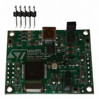
STEVAL-MKI024V1 STMicroelectronics, STEVAL-MKI024V1 Datasheet - Page 21

STEVAL-MKI024V1
Manufacturer Part Number
STEVAL-MKI024V1
Description
DEMO BOARD BASED ON LIS331DL
Manufacturer
STMicroelectronics
Series
MEMSr
Datasheets
1.STEVAL-MKI024V1.pdf
(42 pages)
2.STEVAL-MKI024V1.pdf
(39 pages)
3.STEVAL-MKI024V1.pdf
(4 pages)
Specifications of STEVAL-MKI024V1
Design Resources
STEVAL-MKI024V1 Gerber Files STEVAL-MKI024V1 Schematics STEVAL-MKI024V1 Bill of Materials
Sensor Type
Accelerometer, 3 Axis
Sensing Range
±2.3g, 9.2g
Interface
SPI, USB
Sensitivity
72mg/digit
Voltage - Supply
5V, USB
Embedded
Yes, MCU, 8-Bit
Utilized Ic / Part
LIS331DL
Acceleration
2 g, 8 g
Sensing Axis
Triple Axis
Output Type
Digital
Interface Type
USB
Silicon Manufacturer
ST Micro
Silicon Core Number
LIS331DL
Kit Application Type
Sensing - Motion / Vibration / Shock
Application Sub Type
Accelerometer
Kit Contents
Board
Lead Free Status / RoHS Status
Lead free / RoHS Compliant
Other names
497-8719
Available stocks
Company
Part Number
Manufacturer
Quantity
Price
Company:
Part Number:
STEVAL-MKI024V1
Manufacturer:
STMicroelectronics
Quantity:
135
UM0692
3.10
3.11
“FFT” tab
The FFT tab
The spectral data are updated every sample and are calculated on a 64-sample moving
window.
Figure 20. FFT tab
“Interrupt” tab
The interrupt tab
of the LIS331DL MEMS sensor. In this section of the GUI it is possible to configure the
characteristics of the inertial events that must be recognized by the device and to visualize,
in real-time, the level of the two interrupt lines together with the acceleration signals that are
measured by the device.
The GUI provides direct access to the registers (INT_CFG, INT_SRC, THS and duration)
that allow the configuration
device. Conversion boxes are located on the right-most side of the THS and DURATION
registers
value expressed in mg and the duration value converted in msec for better readability and
understanding.
Finally, two buttons are provided for each interrupt line to set the suggested default values
for free-fall and wakeup detection. Those buttons are marked “Set FreeFall Default” and “Set
Wake Up Default”, respectively
(Figure
(Figure
21, ref 2). These boxes are intended to show, respectively, the threshold
(Figure
20) shows the FFT of the acceleration signals acquired by the sensor.
21) provides a tool for evaluating the interrupt generation features
(Figure
(Figure
21, ref 1) of the two independent interrupt sources of the
21, ref 3).
Graphical user interface
AM01784v1
21/39


