AD8224-EVALZ Analog Devices Inc, AD8224-EVALZ Datasheet - Page 9
AD8224-EVALZ
Manufacturer Part Number
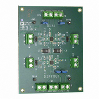
AD8224-EVALZ
Description
BOARD EVALUATION AD8224
Manufacturer
Analog Devices Inc
Specifications of AD8224-EVALZ
Channels Per Ic
2 - Dual
Amplifier Type
Instrumentation
Output Type
Single-Ended, Rail-to-Rail
Slew Rate
2 V/µs
-3db Bandwidth
1.5MHz
Current - Output / Channel
15mA
Operating Temperature
-40°C ~ 85°C
Current - Supply (main Ic)
750µA
Voltage - Supply, Single/dual (±)
4.5 V ~ 36 V, ±2.25 V ~ 18 V
Board Type
Fully Populated
Utilized Ic / Part
AD8224
Silicon Manufacturer
Analog Devices
Application Sub Type
JFET Input Instrumentation Amplifier
Kit Application Type
Amplifier
Silicon Core Number
AD8224
Kit Contents
Board
Lead Free Status / RoHS Status
Lead free / RoHS Compliant
Available stocks
Company
Part Number
Manufacturer
Quantity
Price
Company:

Part Number:
AD8224-EVALZ
Manufacturer:
Analog Devices Inc
Quantity:
135


ABSOLUTE MAXIMUM RATINGS
Table 8.
Parameter
Supply Voltage
Power Dissipation
Output Short-Circuit Current
Input Voltage (Common Mode)
Differential Input Voltage
Storage Temperature Range
Operating Temperature Range
Lead Temperature (Soldering, 10 sec)
Junction Temperature
Package Glass Transition Temperature
ESD (Human Body Model)
ESD (Charge Device Model)
ESD (Machine Model)
Stresses above those listed under Absolute Maximum Ratings
may cause permanent damage to the device. This is a stress
rating only; functional operation of the device at these or any
other conditions above those indicated in the operational
section of this specification is not implied. Exposure to absolute
maximum rating conditions for extended periods may affect
device reliability.
1
2
Assumes the load is referenced to midsupply.
Temperature for
to 125°C, see the
specified performance is −40°C to +
Typical Performance Characteristics
2
85°C. For performance
section.
Rating
±18 V
See Figure 2
Indefinite
±V
±V
−65°C to +130°C
−40°C to +125°C
300°C
130°C
130°C
4 kV
1 kV
0.4 kV
S
S
1
Rev. B | Page 9 of 28
THERMAL RESISTANCE
Table 9.
Exposed Paddle Package
CP-16-13: LFCSP Soldered to Board
CP-16-13: LFCSP Not Soldered to Board
Table 10.
Hidden Paddle Package
CP-16-19: LFCSP
The θ
standard board. If the thermal pad is soldered to the board, it is
also assumed it is connected to a plane. θ
4.4°C/W.
Maximum Power Dissipation
The maximum safe power dissipation for the AD8224 is limited
by the associated rise in junction temperature (T
approximately 130°C, which is the glass transition temperature,
the plastic changes its properties. Even temporarily exceeding
this temperature limit may change the stresses that the package
exerts on the die, permanently shifting the parametric performance
of the amplifiers. Exceeding a temperature of 130°C for an
extended period can result in a loss of functionality. Figure 2
shows the maximum safe power dissipation in the package vs.
the ambient temperature for the LFCSP on a 4-layer JEDEC
standard board.
ESD CAUTION
Figure 2. Maximum Power Dissipation vs. Ambient Temperature
JA
4.0
3.5
3.0
2.5
2.0
1.5
1.0
0.5
values in Table 9 and Table 10 assume a 4-layer JEDEC
0
–60
θ
IS NOT SOLDERED TO BOARD
JA
–40
= 86°C/W WHEN THERMAL PAD
–20
AMBIENT TEMPERATURE (°C)
0
θ
IS SOLDERED TO BOARD
JA
20
= 48°C/W WHEN THERMAL PAD
40
60
JC
80
at the exposed pad is
θ
86
θ
86
48
JA
JA
100
J
) on the die. At
120
AD8224
Unit
°C/W
°C/W
Unit
°C/W
140
Related parts for AD8224-EVALZ
Image
Part Number
Description
Manufacturer
Datasheet
Request
R

Part Number:
Description:
Single Supply, Rail to Rail Low Power FET-Input Op Amp
Manufacturer:
Analog Devices
Datasheet:

Part Number:
Description:
±1.7g Dual-Axis IMEMS Accelerometer Evaluation Board
Manufacturer:
Analog Devices Inc
Datasheet:

Part Number:
Description:
Inertial Sensor Evaluation System
Manufacturer:
Analog Devices Inc
Datasheet:
Part Number:
Description:
Manufacturer:
Analog Devices Inc
Datasheet:
Part Number:
Description:
Manufacturer:
Analog Devices Inc
Datasheet:
Part Number:
Description:
Manufacturer:
Analog Devices Inc
Datasheet:
Part Number:
Description:
Manufacturer:
Analog Devices Inc
Datasheet:
Part Number:
Description:
Manufacturer:
Analog Devices Inc
Datasheet:
Part Number:
Description:
Manufacturer:
Analog Devices Inc
Datasheet:
Part Number:
Description:
Manufacturer:
Analog Devices Inc
Datasheet:
Part Number:
Description:
Manufacturer:
Analog Devices Inc
Datasheet:
Part Number:
Description:
Manufacturer:
Analog Devices Inc
Datasheet:
Part Number:
Description:
Manufacturer:
Analog Devices Inc
Datasheet: