MCP6V01DM-VOS Microchip Technology, MCP6V01DM-VOS Datasheet - Page 16
MCP6V01DM-VOS
Manufacturer Part Number
MCP6V01DM-VOS
Description
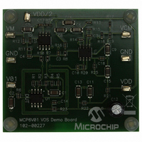
DEMO BOARD FOR MCP6V01
Manufacturer
Microchip Technology
Specifications of MCP6V01DM-VOS
Channels Per Ic
1 - Single
Amplifier Type
Chopper (Zero-Drift)
Output Type
Rail-to-Rail
Slew Rate
0.5 V/µs
Current - Output / Channel
22mA
Operating Temperature
-40°C ~ 125°C
Voltage - Supply, Single/dual (±)
1.8 V ~ 5.5 V
Board Type
Fully Populated
Utilized Ic / Part
MCP6V01
Silicon Manufacturer
Microchip
Application Sub Type
Operational Amplifier
Kit Application Type
Amplifier
Silicon Core Number
MCP6V01, MCP6V03, MCP6V06, MCP6V08
Kit Contents
Board
Lead Free Status / RoHS Status
Lead free / RoHS Compliant
-3db Bandwidth
-
Current - Supply (main Ic)
-
Lead Free Status / Rohs Status
Lead free / RoHS Compliant


MCP6V01 Input Offset Demo Board User’s Guide
2.7
DS51801A-page 12
REDUCING THE MEASUREMENT NOISE
TABLE 2-2:
Obviously, other values of T
to these equations.
The noise seen in the measurements is a result of the design choices made for the
MCP6V01 Input Offset Demo Board. The components R12 and C5 set a lowpass pole
at 0.16 Hz, which gives reasonable noise performance (±0.2 µV
of the DUT) and settling time (1 to 2 seconds).
To achieve lower noise in your results, average many measurements together. For
instance, measuring the output (V
samples) should produce an estimate with noise √16 = 4 times lower (i.e., ±0.05 µV
There is a practical limit on increasing the sample rate; the noise does not improve
significantly after a certain point. The analog lowpass pole at 0.16 Hz causes closely
spaced samples to be correlated. To avoid the overhead caused by sampling too fast,
keep the sampling period near or above the pole’s time constant (1.0s); this gives a
minimum sample rate of 1 sample per second.
Note 1:
1.8 and 5.5
Note:
V
Operating Inputs
5.5
1.8
(V)
DD
V
Sampling much faster than 1 SPS will not improve the averaged noise of
this board’s output significantly.
OST_k
-40 to +125
-40 to +125
ESTIMATES
is calculated from V
+125
(°C)
+25
+25
+85
+25
+25
-40
T
A
A
, V
DD
ΔV
1/CMRR = {(V
1/CMRR = (V
1/PSRR = (V
, … can be used instead, with the proper adjustments
M
OS
1/A
Mk
– V
/ΔT
V
V
V
V
V
OS
OS
OS
OS
OS
using
OL
A
DD
/2) once a second for 16 seconds (16
= 0, by assumption
= V
= V
= V
= V
= (V
= V
Equations (Note 1)
Equation 2-1
OST_8
OST_2
OST_9
OST_10
OST_5
OST_2
OST_10
OST_7
OST_4
Estimate
– V
– V
– V
– V
OST_5
OST_6
.
OST_3
OST_8
© 2009 Microchip Technology Inc.
) / (3.7V)
) / (1.2V)
) / (4.5V)
) / (165°C)
PK
referred to the input
µV/V
µV/V
µV
µV
µV
µV
µV/°C
µV/V
µV
µV/V
Units
PK
).
Related parts for MCP6V01DM-VOS
Image
Part Number
Description
Manufacturer
Datasheet
Request
R

Part Number:
Description:
IC OPAMP AUTO-ZERO SNGL 8SOIC
Manufacturer:
Microchip Technology
Datasheet:

Part Number:
Description:
300 ?A, Auto-Zeroed Op Amps
Manufacturer:
MICROCHIP [Microchip Technology]
Datasheet:
Part Number:
Description:
Op Amps Sngl Auto-Zero Op Amp E temp
Manufacturer:
Microchip Technology

Part Number:
Description:
300 ?a, Auto-zeroed Op Amps
Manufacturer:
Microchip Technology Inc.
Datasheet:
Part Number:
Description:
Manufacturer:
Microchip Technology Inc.
Datasheet:
Part Number:
Description:
Manufacturer:
Microchip Technology Inc.
Datasheet:
Part Number:
Description:
Manufacturer:
Microchip Technology Inc.
Datasheet:
Part Number:
Description:
Manufacturer:
Microchip Technology Inc.
Datasheet:
Part Number:
Description:
Manufacturer:
Microchip Technology Inc.
Datasheet:
Part Number:
Description:
Manufacturer:
Microchip Technology Inc.
Datasheet:
Part Number:
Description:
Manufacturer:
Microchip Technology Inc.
Datasheet: