MCP6XXXEV-AMP4 Microchip Technology, MCP6XXXEV-AMP4 Datasheet - Page 14
MCP6XXXEV-AMP4
Manufacturer Part Number
MCP6XXXEV-AMP4
Description
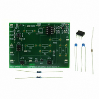
BOARD AMPLIFIER EVAL 4 MCP6XXX
Manufacturer
Microchip Technology
Datasheet
1.MCP6XXXEV-AMP4.pdf
(30 pages)
Specifications of MCP6XXXEV-AMP4
Channels Per Ic
1 - Single
Amplifier Type
General Purpose
Board Type
Partially Populated
Utilized Ic / Part
8-DIP Package
Processor To Be Evaluated
MCP6xxx
Lead Free Status / RoHS Status
Lead free / RoHS Compliant
Operating Temperature
-
Output Type
-
Current - Output / Channel
-
Voltage - Supply, Single/dual (±)
-
-3db Bandwidth
-
Slew Rate
-
Current - Supply (main Ic)
-
Lead Free Status / Rohs Status
Lead free / RoHS Compliant
Available stocks
Company
Part Number
Manufacturer
Quantity
Price
Company:

Part Number:
MCP6XXXEV-AMP4
Manufacturer:
Microchip Technology
Quantity:
135
Company:
Part Number:
MCP6XXXEV-AMP4
Manufacturer:
MICROCHIP
Quantity:
12 000
Part Number:
MCP6XXXEV-AMP4
Manufacturer:
MICROCHIP/微芯
Quantity:
20 000


DS51681A-page 10
2.3.2
• It integrates and inverts a voltage with an integrating frequency
• Figure 2-5 shows the circuit diagram for the inverting integrator block.
FIGURE 2-5:
Table 2-1 shows the jumper positions and the corresponding effects
TABLE 2-1:
Table 2-2 shows the integrator control strategies
TABLE 2-2:
Note 1:
Integrator Control
(rad/s). Additional components control output clipping (wind-up) and initialization
of the integrating capacitor (C
C
JP
Jumper
Feedback Loop
Note 1:
Reset Switch
U1
JP
JP
3
Stand Alone
, JP
Strategy
2:
= 0.1 uF, R
1
2
2:
4
The circuit shown uses a non-inverting comparator to close the feedback loop.
The reset switch (MOSFET) in the circuit is controlled by a non-inverting
comparator.
Inverting Integrator
Adding R
Adding R
Position
(2)
JUMPER POSITIONS AND EFFECTS
INTEGRATOR CONTROL STRATEGY
(1)
V
4
1
2
1
2
3
1
2
= R
CN
V
V
IN
R
Inverting Integrator Block.
T
5
2
3
JP1
= 100.0Ω, M
1
2
2
1
2
to avoid the integrator output clipping at DC.
to minimize the output error due to the input bias current
Set the Input Reference (V
Set the Input Reference (V
Drive Integrator with Comparator
Ground Integrator’s Resistor (contstant input current)
Drive Integrator with External Source
Ground (de-activate) Integrator’s Reset Switch (M
Drive Integrator’s Reset Switch (M
JP3
Jumper Positions
# 1
# 2
R
JP2
R
1
1
1
2
3
3
3
1
100Ω
R5
). Refer to Figure 2-1.
JP3
1
1
1
2
1
1
is N-MOSFET, R
M
1
V
DD
JP4
C
R
1
1
2
1
1
C
U1
1
2
U1
JP4
# 1
# 2
REF
REF
VCMP (internal)
GND (internal)
VINX
Integrator’s Input
100Ω
Inverting Integrator
R
Effect
) to 0.5V
)) to 0.1V
4
3
Voltage
1
= R
) with Comparator
© 2007 Microchip Technology Inc.
1
DD
//R
DD
2
V
ω
OUT
=1/R
open
open
>> R1
1
R2 (Integrator)
)
1
C
1
Related parts for MCP6XXXEV-AMP4
Image
Part Number
Description
Manufacturer
Datasheet
Request
R

Part Number:
Description:
BOARD AMPLIFIER EVAL 3 MCP6XXX
Manufacturer:
Microchip Technology
Datasheet:

Part Number:
Description:
BOARD AMPLIFIER EVAL 1 MCP6XXX
Manufacturer:
Microchip Technology
Datasheet:

Part Number:
Description:
BOARD AMPLIFIER EVAL 2 MCP6XXX
Manufacturer:
Microchip Technology
Datasheet:

Part Number:
Description:
Manufacturer:
Microchip Technology Inc.
Datasheet:
Part Number:
Description:
Manufacturer:
Microchip Technology Inc.
Datasheet:
Part Number:
Description:
Manufacturer:
Microchip Technology Inc.
Datasheet:
Part Number:
Description:
Manufacturer:
Microchip Technology Inc.
Datasheet:
Part Number:
Description:
Manufacturer:
Microchip Technology Inc.
Datasheet:
Part Number:
Description:
Manufacturer:
Microchip Technology Inc.
Datasheet:
Part Number:
Description:
Manufacturer:
Microchip Technology Inc.
Datasheet: