MCP6XXXEV-AMP2 Microchip Technology, MCP6XXXEV-AMP2 Datasheet
MCP6XXXEV-AMP2
Specifications of MCP6XXXEV-AMP2
Available stocks


Related parts for MCP6XXXEV-AMP2


MCP6XXXEV-AMP2 Summary of contents
Page 1
... Microchip Technology Inc. MCP6XXX Amplifier Evaluation Board 2 User’s Guide DS51668A ...
Page 2
... PowerInfo, PowerMate, PowerTool, REAL ICE, rfLAB, Select Mode, Smart Serial, SmartTel, Total Endurance, UNI/O, WiperLock and ZENA are trademarks of Microchip Technology Incorporated in the U.S.A. and other countries. SQTP is a service mark of Microchip Technology Incorporated in the U.S.A. All other trademarks mentioned herein are property of their respective companies. ...
Page 3
... A.3 Board - Top Silk Layer A.4 Board - Top Metal Layer .............................................................................. 26 A.5 Board - Bottom Metal Layer ......................................................................... 27 Appendix B. Bill of Materials (BOM) .......................................................................... 29 B.1 MCP6XXX Amplifier Evaluation Board 2 BOM ............................................ 29 Worldwide Sales and Service .................................................................................... 32 © 2007 Microchip Technology Inc. MCP6XXX AMPLIFIER EVALUATION BOARD 2 USER’S GUIDE Table of Contents .............................................................................. 25 DS51668A-page iii ...
Page 4
... MCP6XXX Amplifier Evaluation Board 2 User’s Guide NOTES: DS51668A-page iv © 2007 Microchip Technology Inc. ...
Page 5
... Appendix A. “Schematic and Layouts” – Shows the schematic and board layouts for the MCP6XXX Amplifier Evaluation Board 2. • Appendix B. “Bill of Materials (BOM)” – Lists the parts used to build the MCP6XXX Amplifier Evaluation Board 2. © 2007 Microchip Technology Inc. MCP6XXX AMPLIFIER EVALUATION BOARD 2 USER’S GUIDE Preface NOTICE TO CUSTOMERS ® ...
Page 6
... Optional arguments mcc18 [options] file [options] Choice of mutually exclusive errorlevel {0|1} arguments selection Replaces repeated text var_name [, var_name...] Represents code supplied by void main (void) user { ... } © 2007 Microchip Technology Inc. Examples ® IDE User’s Guide ...
Page 7
... Local sales offices are also available to help customers. A listing of sales offices and locations is included in the back of this document. Technical support is available through the web site at: http://support.microchip.com DOCUMENT REVISION HISTORY Revision A (July 2007) • Initial Release of this Document. © 2007 Microchip Technology Inc. Preface DS51668A-page 3 ...
Page 8
... MCP6XXX Amplifier Evaluation Board 2 User’s Guide NOTES: DS51668A-page 4 © 2007 Microchip Technology Inc. ...
Page 9
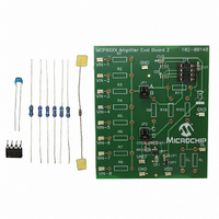
... INTRODUCTION The MCP6XXX Amplifier Evaluation Board 2 is described by the following: • Assembly # : 114-00148 • Order # : MCP6XXXEV-AMP2 • Name: MCP6XXX Amplifier Evaluation Board 2 Items discussed in this chapter include: • Section 1.2 “MCP6XXX Amplifier Evaluation Board 2 Kit Contents” • Section 1.3 “Microchip’s Web-Based Mindi™ Analog Simulator Tool” ...
Page 10
... DS51668A-page 6 http://www.microchip.com under “Online Simulation Tools” or Amplifier Circuit (Op Amp, Resistors, Capacitors and Jumpers) Mid-Supply Ref Power Supply and and Test Point Test Point MCP6XXX Amplifier Evaluation Board 2 Block Diagram. Signal Output and Test Point © 2007 Microchip Technology Inc. ...
Page 11
... Test Points R1 VIN-1 R2 VIN-2 R3 VIN-3 R4 VIN-4 R5 VIN-5 R6 VIN-6 R7 VIN-7 R8 VIN-8 FIGURE 2-1: © 2007 Microchip Technology Inc. MCP6XXX AMPLIFIER EVALUATION BOARD 2 USER’S GUIDE GND JP1 JP2 C D VDD 0.1 µF RR1 20 kΩ CR1 CR2 RR2 UR1 20 kΩ ...
Page 12
... The (surface mount) test points for power supply, ground, input signal and output signal allow lab equipment to be connected to the board. The MCP6XXX Amplifier Evaluation Board 2 top view is shown in Figure 2-2. FIGURE 2-2: DS51668A-page 8 MCP6XXX Amplifier Evaluation Board 2 Top View. © 2007 Microchip Technology Inc. ...
Page 13
... FIGURE 2-3: 2.3.1.2 MID-SUPPLY REFERENCE BLOCK The mid-supply reference consists of a voltage divider and a buffer amplifier. Figure 2-4 shows the circuit diagram for the mid-supply reference 0.1 µ FIGURE 2-4: © 2007 Microchip Technology Inc. Installation and Operation Power Supply Note zener diode with nominal voltage of 6 ...
Page 14
... The output load consists of a capacitor and two resistors. Figure 2-5 shows the circuit diagram for the output load. R capacitive load (C FIGURE 2-5: DS51668A-page 10 is used to stabilize the amplifier when it drives a large ISO ). short circuit (0Ω) when C L ISO Output Load R V ISO OUT Output Load Block. is small © 2007 Microchip Technology Inc. ...
Page 15
... Figure 2-7 shows an example of the inverting summing amplifier circuit diagram sup- ported by MCP6XXX Amplifier Evaluation Board 2. * Test Points R1 VIN-1 R2 VIN-2 R3 VIN-3 R4 VIN-4 R5 VIN-5 R6 VIN-6 R7 VIN-7 R8 VIN-8 FIGURE 2-7: MCP6XXX Amplifier Evaluation Board 2. © 2007 Microchip Technology Inc. Installation and Operation V DD Power Supply OUT ...
Page 16
... CR1 VREF CR2 RR2 UR1 20 kΩ 0.1 µF GND Non-Inverting Summing Amplifier Example Supported by the V S Output V L Load VDD 0.1 µF CU1 U1 R11 GND RISO Power Supply CP1 DP1 * 1.0 µF VDD © 2007 Microchip Technology Inc. ...
Page 17
... Power Supply Voltage is 5.0V • Desired Gain for V • Desired Gain for V • Desired Gain for V • Load Capacitance FIGURE 2-10: Inverting Summing Amplifier Designed In the Mindi™ Amplifier Designer. © 2007 Microchip Technology Inc. Installation and Operation is 1 V/V IN V/V IN V/V ...
Page 18
... Inverting Summing Amplifier Supported by the MCP6XXX AMPLIFIER COMPONENTS LIST R1 7.96 kΩ R2 7.96 kΩ R3 7.96 kΩ R9 2.00 kΩ R11 7.96 kΩ RISO 0Ω RL 7.96 kΩ MCP6021, PDIP-8, 10 MHz JUMPER POSITIONS Position Power Supply V OUT Output V L Load Component Values © 2007 Microchip Technology Inc. ...
Page 19
... VIN-6 R7 VIN-7 R8 VIN-8 FIGURE 2-12: MCP6XXX Amplifier Evaluation Board 2. The fully assembled MCP6XXX Amplifier Evaluation Board 2 top view is shown in Figure 2-13. FIGURE 2-13: MCP6XXX Amplifier Evaluation Board 2. © 2007 Microchip Technology Inc. Installation and Operation GND JP1 R10 JP2 C D VDD 0.1 µ ...
Page 20
... Figure 2-14 shows the test points to check. FIGURE 2-14: DS51668A-page 16 GND Test Point VREF GND VDD Test Point Test Point Test Point Checking the Test Points. GND Test Point VL Test Point © 2007 Microchip Technology Inc. ...
Page 21
... V and ends 2.1V below center) Note: The center voltage REF 2.5V REF V = 0.4V OUT FIGURE 2-15: © 2007 Microchip Technology Inc. Installation and Operation is set REF = 2.5V) Measured Step Response. starts IN starts 2.1V above center OUT = V /2 (For V = 5.0V ...
Page 22
... V and ends 2.1V below center) Note: The center voltage REF REF V OUT FIGURE 2-16: DS51668A-page 18 is set REF = 2.5V) = 3.2V = 2.5V = 0.4V Simulated Step Response. starts IN starts 2.1V above center OUT = V /2 (For V = 5.0V © 2007 Microchip Technology Inc. ...
Page 23
... The measured sine wave response is shown in Figure 2-17 sine wave signal with a frequency of 100.0 Hz, a peak-to-peak voltage of 4.2V and a center voltage of 2.5V Note: The center voltage REF FIGURE 2-17: © 2007 Microchip Technology Inc. Installation and Operation is set REF = 2.5V) OUT V REF Measured Sine Wave Response (For ...
Page 24
... The simulated sine wave response is shown in Figure 2-18 sine wave signal with a frequency of 100.0 Hz, a peak-to-peak voltage of 4.2V and a center voltage of 2.5V Note: The center voltage REF V OUT V FIGURE 2-18: DS51668A-page 20 is set REF = 2.5V REF Simulated Sine Wave Response (For V = 5.0V © 2007 Microchip Technology Inc. ...
Page 25
... Evaluation Board 2. Figure 2-20 shows a SOIC-8 op amp and a DIP-8 socket, soldered onto the 8-Pin SOIC/MSOP/TSSOP/DIP Evaluation Board available from Microchip Technology Inc. (order # SOIC8EV). The two interconnect strips on the bottom are Samtec part # BBS-14-T-B or equivalent and are soldered into the through holes for the DIP-8 socket. ...
Page 26
... MCP6XXX Amplifier Evaluation Board 2 User’s Guide FIGURE 2-20: FIGURE 2-21: Board 2. DS51668A-page 22 (Front View) Op Amp in SOIC-8 package soldered to a separate board. Connecting Adaptor Board onto MCP6XXX Amplifier Evaluation (Back View) © 2007 Microchip Technology Inc. ...
Page 27
... This appendix contains the following schematics and layouts for the MCP6XXX Ampli- fier Evaluation Board 2: • Board – Schematic • Board – Top Silk Layer • Board – Top Metal Layer • Board – Bottom Metal Layer © 2007 Microchip Technology Inc. MCP6XXX AMPLIFIER EVALUATION BOARD 2 USER’S GUIDE DS51668A-page 23 ...
Page 28
... MCP6XXX Amplifier Evaluation Board 2 User’s Guide A.2 BOARD - SCHEMATIC DS51668A-page 24 © 2007 Microchip Technology Inc. ...
Page 29
... A.3 BOARD - TOP SILK LAYER © 2007 Microchip Technology Inc. Schematic and Layouts DS51668A-page 25 ...
Page 30
... MCP6XXX Amplifier Evaluation Board 2 User’s Guide A.4 BOARD - TOP METAL LAYER DS51668A-page 26 © 2007 Microchip Technology Inc. ...
Page 31
... A.5 BOARD - BOTTOM METAL LAYER © 2007 Microchip Technology Inc. Schematic and Layouts DS51668A-page 27 ...
Page 32
... MCP6XXX Amplifier Evaluation Board 2 User’s Guide NOTES: DS51668A-page 28 © 2007 Microchip Technology Inc. ...
Page 33
... U1 IC Socket, 8-position DIP, Tin Note 1: The components listed in this Bill of Materials are representative of the PCB assembly. The released BOM used in manufacturing uses all RoHS-compliant components. © 2007 Microchip Technology Inc. MCP6XXX AMPLIFIER EVALUATION BOARD 2 USER’S GUIDE Description Manufacturer ® ...
Page 34
... RoHS-compliant components. DS51668A-page 30 Description Manufacturer Microchip Technology Inc MCP6021-E/P Microchip Technology Inc MCP6021-E/SN — Description Manufacturer Murata Electronics Yageo Corporation Yageo Corporation Yageo Corporation Microchip Technology Inc. MCP6021-E/P Part Number — Part Number RPE5C1H560J2P1Z03B ZOR-12-B-52 MFR-25FBF-2K00 MFR-25FBF-7K87 © 2007 Microchip Technology Inc. ...
Page 35
... NOTES: © 2007 Microchip Technology Inc. Bill of Materials (BOM) DS51668A-page 31 ...
Page 36
... Fax: 886-3-572-6459 Taiwan - Kaohsiung Tel: 886-7-536-4818 Fax: 886-7-536-4803 Taiwan - Taipei Tel: 886-2-2500-6610 Fax: 886-2-2508-0102 Thailand - Bangkok Tel: 66-2-694-1351 Fax: 66-2-694-1350 © 2007 Microchip Technology Inc. EUROPE Austria - Wels Tel: 43-7242-2244-39 Fax: 43-7242-2244-393 Denmark - Copenhagen Tel: 45-4450-2828 Fax: 45-4485-2829 France - Paris Tel: 33-1-69-53-63-20 ...