MCP6XXXEV-AMP4 Microchip Technology, MCP6XXXEV-AMP4 Datasheet
MCP6XXXEV-AMP4
Specifications of MCP6XXXEV-AMP4
Available stocks


Related parts for MCP6XXXEV-AMP4


MCP6XXXEV-AMP4 Summary of contents
Page 1
... Microchip Technology Inc. MCP6XXX Amplifier Evaluation Board 4 User’s Guide DS51681A ...
Page 2
... Mate, PowerTool, REAL ICE, rfLAB, Select Mode, Smart Serial, SmartTel, Total Endurance, UNI/O, WiperLock and ZENA are trademarks of Microchip Technology Incorporated in the U.S.A. and other countries. SQTP is a service mark of Microchip Technology Incorporated in the U.S.A. All other trademarks mentioned herein are property of their respective companies. ...
Page 3
... A.3 Board - Top Silk and Metal Layers A.4 Board - Top Metal Layer .............................................................................. 20 A.5 Board - Bottom Metal Layer ......................................................................... 21 Appendix B. Bill of Materials (BOM) .......................................................................... 23 B.1 MCP6XXX Amplifier Evaluation Board 4 BOM ............................................ 23 Worldwide Sales and Service .................................................................................... 27 © 2007 Microchip Technology Inc. MCP6XXX AMPLIFIER EVALUATION BOARD 4 USER’S GUIDE Table of Contents ........................................................... 19 DS51681A-page iii ...
Page 4
... NOTES: DS51681A-page iv © 2007 Microchip Technology Inc. ...
Page 5
... Appendix A. “Schematic and Layouts” – Shows the schematic and board layouts for the MCP6XXX Amplifier Evaluation Board 4. • Appendix B. “Bill of Materials (BOM)” – Lists the parts used to build the MCP6XXX Amplifier Evaluation Board 4. © 2007 Microchip Technology Inc. MCP6XXX AMPLIFIER EVALUATION BOARD 4 USER’S GUIDE Preface NOTICE TO CUSTOMERS ® ...
Page 6
... Optional arguments mcc18 [options] file [options] Choice of mutually exclusive errorlevel {0|1} arguments selection Replaces repeated text var_name [, var_name...] Represents code supplied by void main (void) user { ... } © 2007 Microchip Technology Inc. Examples ® IDE User’s Guide ...
Page 7
... Local sales offices are also available to help customers. A listing of sales offices and locations is included in the back of this document. Technical support is available through the web site at: http://support.microchip.com DOCUMENT REVISION HISTORY Revision A (August 2007) • Initial Release of this Document. © 2007 Microchip Technology Inc. DS51681A-page 3 ...
Page 8
... NOTES: DS51681A-page 4 © 2007 Microchip Technology Inc. ...
Page 9
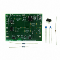
... INTRODUCTION The MCP6XXX Amplifier Evaluation Board 4 is described by the following: • Assembly # : 114-00154 • Order # : MCP6XXXEV-AMP4 • Name: MCP6XXX Amplifier Evaluation Board 4 Items discussed in this chapter include: • Section 1.2 “MCP6XXX Amplifier Evaluation Board 4 Kit Contents” • Section 1.3 “MCP6XXX Amplifier Evaluation Board 4 Description” ...
Page 10
... Lab equipment can be attached (via test points) to measure the amplifier response. FIGURE 1-2: DS51681A-page 6 Power Supply Non-Inverting and Comparator Test Point Block Amplifier (Op Amp, Resistors and Capacitors) Signal Inputs Signal Output and Test Points Test Points MCP6XXX Amplifier Evaluation Board 4 Block Diagram. and © 2007 Microchip Technology Inc. ...
Page 11
... MCP6XXX Amplifier Evaluation Board 4. Figure 2-1 shows the circuit diagram for the board. VDD Power Supply VDD RV1 10k RV2 8k RV3 2k GND VINX GND FIGURE 2-1: © 2007 Microchip Technology Inc. MCP6XXX AMPLIFIER EVALUATION BOARD 4 USER’S GUIDE Block VDD VREF JP1 0.1 µF JP2 R1 1 ...
Page 12
... The MCP6XXX Amplifier Evaluation Board 4 top view is shown in Figure 2-2. FIGURE 2-2: DS51681A-page 8 ) and two resistors ( small. MCP6XXX Amplifier Evaluation Board 4 Top View used L ISO ISO is a short circuit ISO and 0. © 2007 Microchip Technology Inc. ...
Page 13
... FIGURE 2-3: 2.3.1.2 NON-INVERTING COMPARATOR Figure 2-4 shows the circuit diagram for the non-inverting comparator block. The non-inverting comprator’s trip points are 0. 10.0 kΩ FIGURE 2-4: © 2007 Microchip Technology Inc. Power Supply Note zener diode with nominal voltage of 6.2V P1 Power Supply Block ...
Page 14
... INTEGRATOR CONTROL STRATEGY Jumper Positions JP1 JP2 JP3 JP4 ( ( ω Inverting Integrator V OUT R 4 100Ω Effect ) to 0.5V REF 0.1V REF with Comparator 1 Integrator’s Input R2 (Integrator) Voltage VCMP (internal) open GND (internal) open VINX >> R1 © 2007 Microchip Technology Inc. ...
Page 15
... Integrator Control Strategy: Feedback Loop (JP1: Position 1, JP2: Position 1, JP3: Position 1, JP4: Position 1) • The fully assembled inverting integrator is shown in Figure 2-6. VDD Power Supply VDD RV1 10k RV2 8k RV3 2k GND VINX GND FIGURE 2-6: Amplifier Evaluation Board 4. © 2007 Microchip Technology Inc 1.6 k Ω L μ open 8.06 k Ω ...
Page 16
... The fully assembled MCP6XXX Amplifier Evaluation Board 4 top view is shown in Figure 2-7 (without any user selected components). FIGURE 2-7: Amplifier Evaluation Board 4. DS51681A-page 12 Picture of the Inverting Integrator Supported by the MCP6XXX © 2007 Microchip Technology Inc. ...
Page 17
... INVERTING INTEGRATOR RESPONSE The MCP6021 op amp, 1% resistors, and 5% capacitors were used to build an inverting integrator circuit. The measured response with feedback control strategy is shown in Figure 2- 2. FIGURE 2-9: © 2007 Microchip Technology Inc. Test VREF Test VSW Checking the Test Points REF Measured Output Response ...
Page 18
... Evaluation Board 4. Figure 2-11 shows a SOIC-8 op amp and a DIP-8 socket, soldered onto the 8-Pin SOIC/MSOP/TSSOP/DIP Evaluation Board available from Microchip Technology Inc. (order # SOIC8EV). The two interconnect strips on the bottom are Samtec part # BBS-14-T-B or equivalent and are soldered into the through holes for the DIP-8 socket. ...
Page 19
... FIGURE 2-11: FIGURE 2-12: Board 4. © 2007 Microchip Technology Inc. (Front View) Op Amp in SOIC-8 package soldered to a separate board. Connecting Adaptor Board onto MCP6XXX Amplifier Evaluation (Back View) DS51681A-page 15 ...
Page 20
... NOTES: DS51681A-page 16 © 2007 Microchip Technology Inc. ...
Page 21
... This appendix contains the following schematics and layouts for the MCP6XXX Amplifier Evaluation Board 4: • Board – Schematic • Board – Top Silk and Metal Layers • Board – Top Metal Layer • Board – Bottom Metal Layer © 2007 Microchip Technology Inc. MCP6XXX AMPLIFIER EVALUATION BOARD 4 USER’S GUIDE DS51681A-page 17 ...
Page 22
... MCP6XXX Amplifier Evaluation Board 4 User’s Guide A.2 BOARD - SCHEMATIC 3 1 DS51681A-page 18 © 2007 Microchip Technology Inc. ...
Page 23
... A.3 BOARD - TOP SILK AND METAL LAYERS © 2007 Microchip Technology Inc. DS51681A-page 19 ...
Page 24
... MCP6XXX Amplifier Evaluation Board 4 User’s Guide A.4 BOARD - TOP METAL LAYER DS51681A-page 20 © 2007 Microchip Technology Inc. ...
Page 25
... A.5 BOARD - BOTTOM METAL LAYER © 2007 Microchip Technology Inc. DS51681A-page 21 ...
Page 26
... MCP6XXX Amplifier Evaluation Board 4 User’s Guide NOTES: DS51681A-page 22 © 2007 Microchip Technology Inc. ...
Page 27
... For U1 CONN IC SOCKET 8POS DIP TIN Note 1: The components listed in this Bill of Materials are representative of the PCB assembly. The released BOM used in manufacturing uses all RoHS-compliant components. © 2007 Microchip Technology Inc. MCP6XXX AMPLIFIER EVALUATION BOARD 4 USER’S GUIDE Description Manufacturer ...
Page 28
... RoHS-compliant components. DS51681A-page 24 Description Manufacturer Microchip Technology Inc — Description Manufacturer Murata Electronics ® TDK Corporation ® Yageo Corporation Yageo Corporation Yageo Corporation Draft Part Number MCP6021-E/P — Part Number ® RPE5C1H560J2P1Z03B FK24X7R1E105K ZOR-12-B-52 MFR-25FBF-8K06 MFR-25FBF-1K58 © 2007 Microchip Technology Inc. ...
Page 29
... NOTES: © 2007 Microchip Technology Inc. Draft DS51681A-page 25 ...
Page 30
... Fax: 886-3-572-6459 Taiwan - Kaohsiung Tel: 886-7-536-4818 Fax: 886-7-536-4803 Taiwan - Taipei Tel: 886-2-2500-6610 Fax: 886-2-2508-0102 Thailand - Bangkok Tel: 66-2-694-1351 Fax: 66-2-694-1350 © 2007 Microchip Technology Inc. EUROPE Austria - Wels Tel: 43-7242-2244-39 Fax: 43-7242-2244-393 Denmark - Copenhagen Tel: 45-4450-2828 Fax: 45-4485-2829 France - Paris Tel: 33-1-69-53-63-20 ...