SOT23-5EV-VREG Microchip Technology, SOT23-5EV-VREG Datasheet - Page 5
SOT23-5EV-VREG
Manufacturer Part Number
SOT23-5EV-VREG
Description
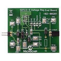
EVAL BOARD SOT23-5 VOLTAGE REG
Manufacturer
Microchip Technology
Datasheet
1.SOT23-5EV-VREG.pdf
(24 pages)
Specifications of SOT23-5EV-VREG
Channels Per Ic
1 - Single
Regulator Type
Positive Fixed & Adjustable
Board Type
Partially Populated
Utilized Ic / Part
SOT-23-5 Package
Silicon Manufacturer
Microchip
Application Sub Type
Voltage Regulator
Kit Application Type
Power Management - Voltage Regulator
Silicon Core Number
MCP1801, MCP1802, TC1014/1015/1185
Lead Free Status / RoHS Status
Lead free / RoHS Compliant
Current - Output
-
Voltage - Output
-
Voltage - Input
-
Operating Temperature
-
Lead Free Status / Rohs Status
Lead free / RoHS Compliant


INTRODUCTION
DOCUMENT LAYOUT
© 2009 Microchip Technology Inc.
All documentation becomes dated, and this manual is no exception. Microchip tools and
documentation are constantly evolving to meet customer needs, so some actual dialogs
and/or tool descriptions may differ from those in this document. Please refer to our web site
(www.microchip.com) to obtain the latest documentation available.
Documents are identified with a “DS” number. This number is located on the bottom of each
page, in front of the page number. The numbering convention for the DS number is
“DSXXXXXA”, where “XXXXX” is the document number and “A” is the revision level of the
document.
For the most up-to-date information on development tools, see the MPLAB
Select the Help menu, and then Topics to open a list of available on-line help files.
This chapter contains general information that will be useful to know before using the
SOT23-5 Voltage Regulator Evaluation Board. Items discussed in this chapter include:
• Document Layout
• Conventions Used in this Guide
• Recommended Reading
• The Microchip Web Site
• Customer Support
• Document Revision History
This document describes how to use the SOT23-5 Voltage Regulator Evaluation Board
as a development tool to emulate and debug firmware on a target board. The manual
layout is as follows:
• Chapter 1. “Product Overview” – Important information about the SOT23-5
• Chapter 2. “Installation and Operation” – This chapter includes a detailed
• Appendix A. “Schematic and Layouts”– Shows the schematic and layout
• Appendix B. “Bill of Materials (BOM)” – Lists the parts used to build the
Voltage Regulator Evaluation Board.
description of each function of the demo board and instructions for how to begin
using the board.
diagrams for the SOT23-5 Voltage Regulator Evaluation Board.
SOT23-5 Voltage Regulator Evaluation Board.
EVALUATION BOARD USER’S GUIDE
NOTICE TO CUSTOMERS
SOT23-5 VOLTAGE REGULATOR
Preface
®
IDE on-line help.
DS51811A-page 1
Related parts for SOT23-5EV-VREG
Image
Part Number
Description
Manufacturer
Datasheet
Request
R


Part Number:
Description:
SOT23/E/ECONRST 3.3V 5% CMOS OUT SOT23 T&R
Manufacturer:
Maxim Integrated Products
Datasheet:
Part Number:
Description:
SOT23-6/A�/20MBPS +3.3V SOT23 RS-485/RS-422 TRANSMITTERS
Manufacturer:
Maxim Integrated Products
Datasheet:
Part Number:
Description:
SOT23-8/A�/Low-Voltage, SOT23, �P Supervisors
Manufacturer:
Maxim Integrated Products
Part Number:
Description:
SOT23/E/ECONORST 3.3V-10% W/PBRST SOT23 T&R
Manufacturer:
Maxim Integrated Products

Part Number:
Description:
SOT23, Low-Power uP Supervisory Circuits with Battery Backup and Chip-Enable Gating
Manufacturer:
Maxim Integrated Products
Datasheet:
Part Number:
Description:
SOT23, Low-Power uP Supervisory Circuits with Battery Backup and Chip-Enable Gating
Manufacturer:
Maxim Integrated Products
