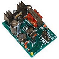
IRPLLED1 International Rectifier, IRPLLED1 Datasheet - Page 19

IRPLLED1
Manufacturer Part Number
IRPLLED1
Description
BOARD EVALUATION FOR IRS2540PBF
Manufacturer
International Rectifier
Specifications of IRPLLED1
Current - Output / Channel
1.5A
Outputs And Type
1, Non-Isolated
Voltage - Output
24V
Features
Dimmable
Voltage - Input
50 ~ 170V
Utilized Ic / Part
IRS2540PBF
Core Chip
IRS2540, IRS2541, IRS25401
Topology
Buck (Step Down)
No. Of Outputs
1
Output Current
1.5A
Output Voltage
500mV
Dimming Control Type
PWM
Development Tool Type
Hardware - Eval/Demo Board
Lead Free Status / RoHS Status
Contains lead / RoHS compliant by exemption
If the IRS2540/1/01/11 is supplied from the output, a large enough capacitor on VCC is required to maintain
sufficient current while in a disabled state. For this evaluation board where the IC supply comes from the output, a
10uF capacitor is used to ensure continued operation while disabled. The output is capable of dropping to roughly
10V. A “strobe light” effect in the LEDs may be observed if VCC drops too much or if the dimming frequency is
too low.
Since the IRS2540/1/01/11 does not include an onboard oscillator, a soft start feature is not easily implemented. This
is only a concern when operating in the dimming mode. Since PWM dimming is required of LEDs, the output is
essentially turning on and off at a rate of the dimming frequency. In the absence of soft start a large spike of current
would be observed in the load each time the output is turned on. This current spike stresses the load possibly
decreasing LED operating lifetime. The IRPLLED1 includes a jumper setting to define whether or not the board is
being used in the dimming mode. This two position jumper allows the designer to either include or exclude the
resistor Rout, which is in series with the output capacitor. The inclusion of this resistor will sufficiently damp the
www.irf.com
100
90
80
70
60
50
40
30
20
10
Duty
HO
0
0
Fig. 23 Light Output vs Enable Pin Duty Cycle
on
Cycle
time
10
Enable Duty Cycle Relationship to Light Output
Fig. 24 IRS2540 Dimming Signals
=
20
20
=
RD-0608
%
V
V
out
30
in
*
Percentage of Light Output
1
∗
75
100
40
kHz
=
50
100
=
20
2
V
V
7 .
60
μ
*
s
100
70
=
80
20
%
90
100
19


